CALOR 40 Manual Page 16 (total 27) COMAC CAL s.r.o.
connected to terminals 90 and 91. The current output must be fed from an external power
supply. The external power supply U
e
voltage can be within 12 to 24 V.
The loop resistance must not be higher than R = U
e
/ 0.02 (Ω;V).
As a standard, it is adjusted in such a way that with the maximum flow Q
max
the loop current
is 20mA and with zero or negative flows, the loop current is 4mA. The limits can be set up
by user software.
The value of the current is directly proportional to the value of the flow in the sample.
As the converter is fully digital, it will save the last value also after flow meter power loss.
For the sake of a failure, it is possible to use the failure status output which can be connected
with the current output in series and thus detect the error state with a higher-level system.
Output - Failure
The output is implemented by an optocoupler with an NPN switching transistor, the collector
of which is connected to terminal 70 and the emitter to terminal 71. Limit parameters of this
optocoupler are identical to the parameters of the pulse output. The optocoupler is closed
during the trouble-free operation. The optocoupler is open when there is a failure (such as
power loss).
The failure-output on the meter is brought out only when the meter has no MBUS
communication interface.
Data output
The CALOR40 meters support several communication protocols and physical interfaces.
Physical layer types:
1) MBus
2) RS485
3) RS422
4) IrDa
5) GSM
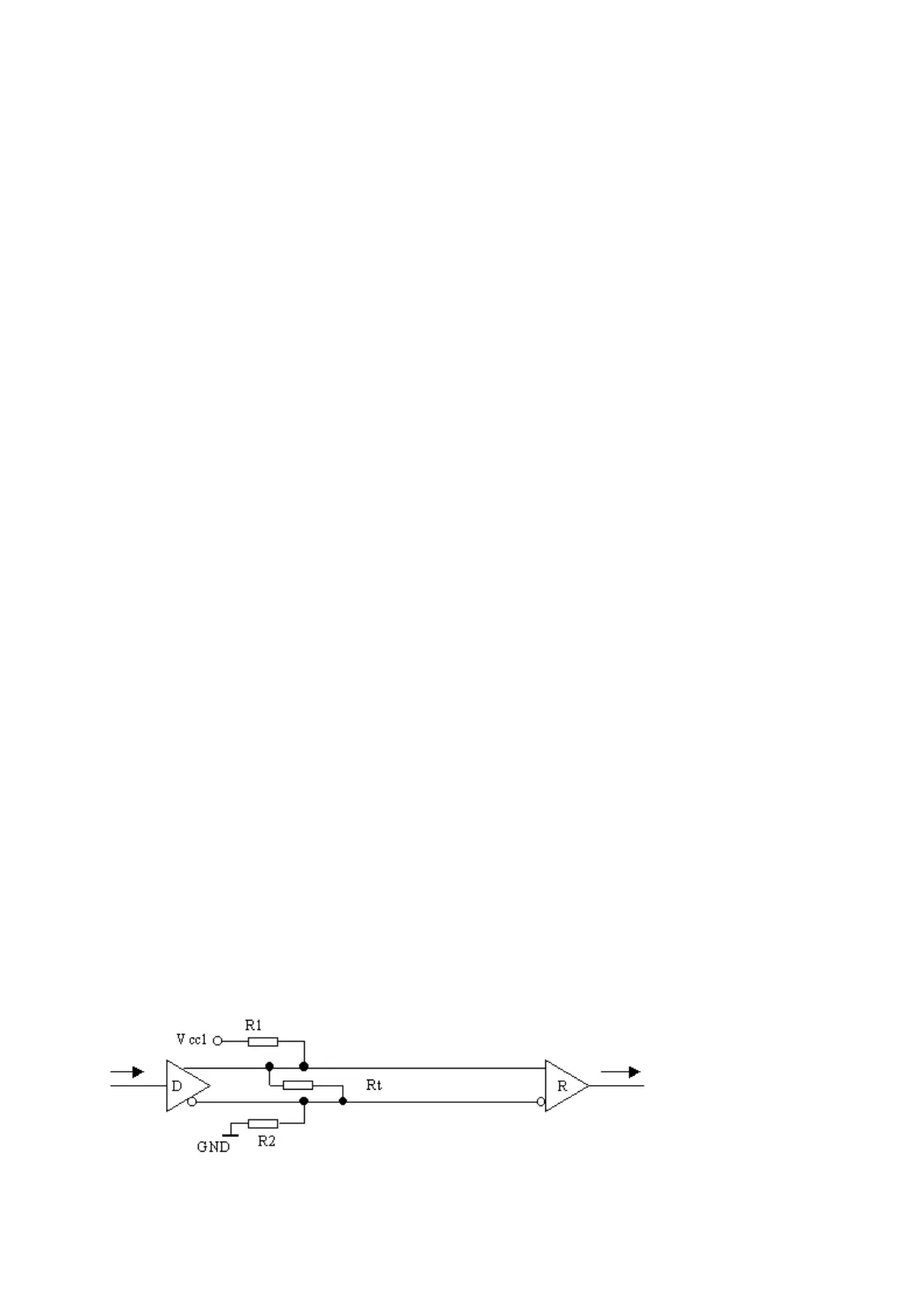
Note to RS485/422 physical layer*)
The connection of Rt terminators to the line ends are recommended. These resistors can be
activated on CALOR40 meters using the integrated jumper. Owing to bit rates, the
terminators do not serve for impedance matching (echo elimination), but for definition of
levels with disconnected drivers during networking.
For definition of idle state with disconnected drivers it is recommended to connect resistors
R1 and R2 to conductors A and B with a value of 1-2k on the control equipment side.