CALOR 40 Manual Page 5 (total 27) COMAC CAL s.r.o.
will not be able to process correctly and promptly your requirement for modification and/or
repair of your meter.
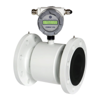
In-pipe installation
Relevant information for selection of location
!!! In the event of the separate construction, the cable must not be lengthened or shortened !!!
Outdoor conditions
It is necessary to prevent the flow sensor from being directly exposed to weather conditions
and prevent the liquid to be measured from freezing over inside the flow sensor, which might
damage the measuring tube.
In the case that the Electronic Evaluation Unit is located outdoors, the manufacturer
recommends a protective case, and if appropriate, a roof to avoid direct sunshine so that the
evaluation electronics cannot warm up excessively.
Sources of disturbance
These are the sources disturbing the steady flow of a liquid:
· Pumps and bends or elbows located closely in series in various planes. These
elements should be at a distance of at least 20d (“d” stands for inside diameter of the
sensor in mm) before the flow sensor.
· Sudden variations in the pipe section unless constructed as a cone with angle
16° (where is the angle between the bevelled walls of the pipe adapter).
· Incorrectly centred seal, the seal with a mall internal diameter, or the seal made of
Soft elastic materials which penetrate into internal section of the pipe after the
flanges have been tightened.
· Anything that interferes with the flow of liquid, e.g. the thermometer well.
· Branches, T-pieces, bends, elbows, slide valves, taps, and throttles. Shut-off valves,
control valves, butterfly valves, and check valves. Pipe outlets from tanks, heat
exchangers, and filters.
No strong electromagnetic field must take effect close to the inductive flow sensor (pick-up).
Vibrations
We recommend you to support the connecting pipes at both sides of the meter to partially
eliminate vibrations. The level and range of vibrations must be below 2.2g within frequency
range of 20 ÷ 50 Hz according to IEC 068-2-34 standard.
Proper location
The flow sensor must not be at the top of the pipeline where air intake occurs or in the
declining and also in horizontal pipeline with open end where air may penetrate.
Sedimentation of impurities may occur during a long-run measurement of very low flow rates
Q < 0.1 m/s. The site where the flow sensor is installed there must be a sufficient pressure so
that vapour or gas bubbles cannot be discharged from the liquid. The tiny bubbles occurring
in liquids all the time can accumulate at any of the electrodes and they can cause incorrect
function of the meter. The gas bubbles are discharged from liquids also during a sudden drop