CALOR 40 Manual Page 6 (total 27) COMAC CAL s.r.o.
of pressure. Therefore, the control butterfly valves and similar components should be inserted
behind the flow sensor. For the same reason, the flow sensor should not be installed at the
suction side of the pump. To prevent the bubbles from accumulating in the flow sensor while
the flow is slow, it is useful for the pipeline either to be slightly ascending or the sensor is put
into the vertical part of the pipeline.
If the meter is populated with measuring electrodes only (2 or 3 electrodes located beyond
the upper profile of the tube), it is necessary for proper function of the meter, to fill up the
flow sensor with the fluid to be measured so that erroneous measurement of quantity of liquid
passing through the meter can be avoided when the pipe is empty. It is necessary to select the
location of the meter in such a way that the flow sensor aeration is avoided.
In the case of an open system, the flow sensor is placed in the bottom position of the U-
profile, ensuring that the fluid will not flow out of the sensor.
Examples of installation
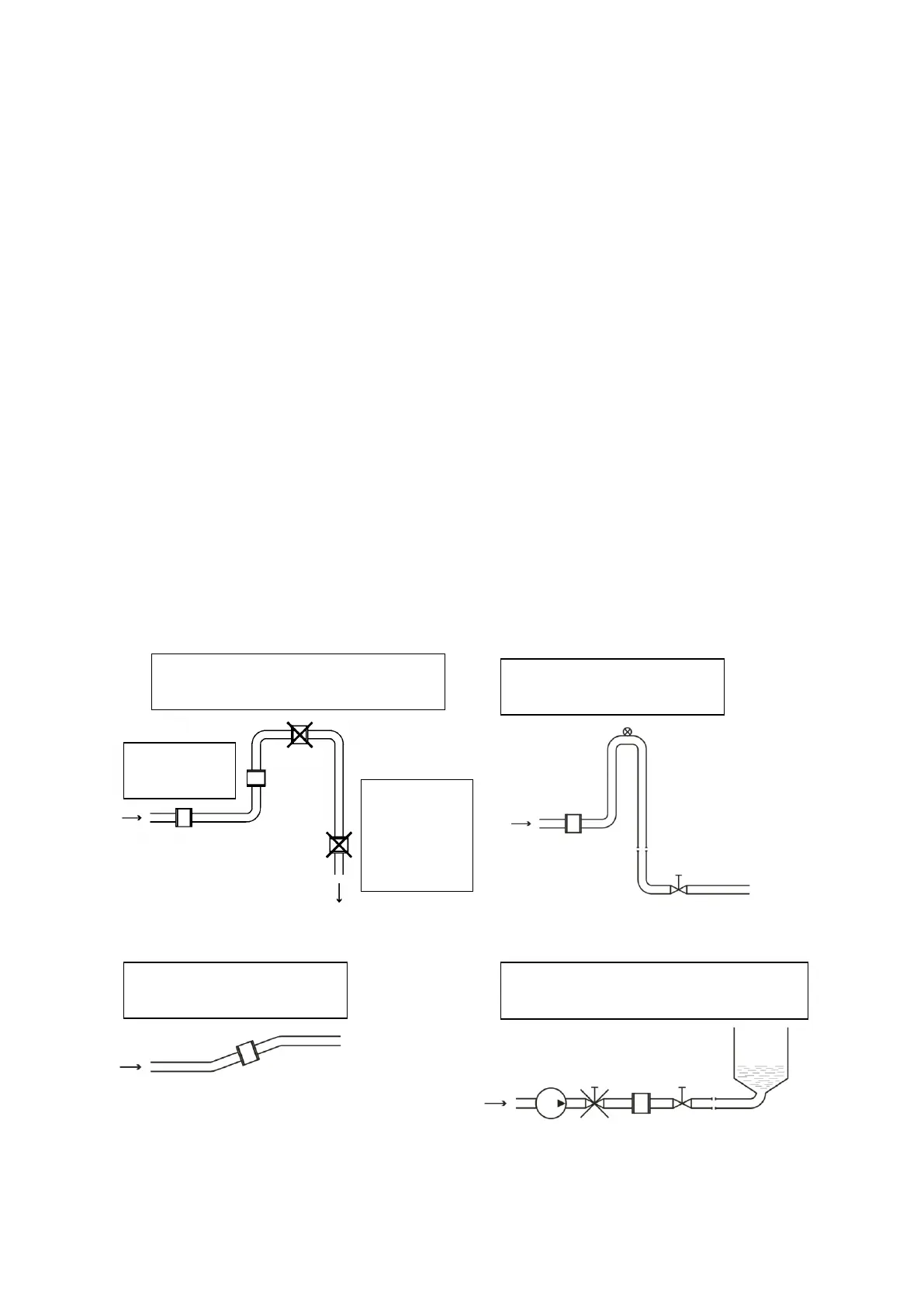
The trouble free and accurate operation of the meter depends on correct location in the
system, especially when the internal PTFE or rubber lining is used where there is a risk of
damage as a result of negative pressure. The most frequent methods of positioning are
illustrated in the following figures:
Recommended positions for installation Down pipe
Horizontally positioned pipe Long pipe
(bubbles are accumulated in the
pipe; erroneous measurement)
Install a purge valve
behind the sensor
Place the sensor into a
slightly ascending pipe
Pipe is
empty;
erroneous
measuring
Always install the control and shut-
off components behind the sensor