INSTALLATION GUIDE FOR RX-1839
Copyright - refer to title page
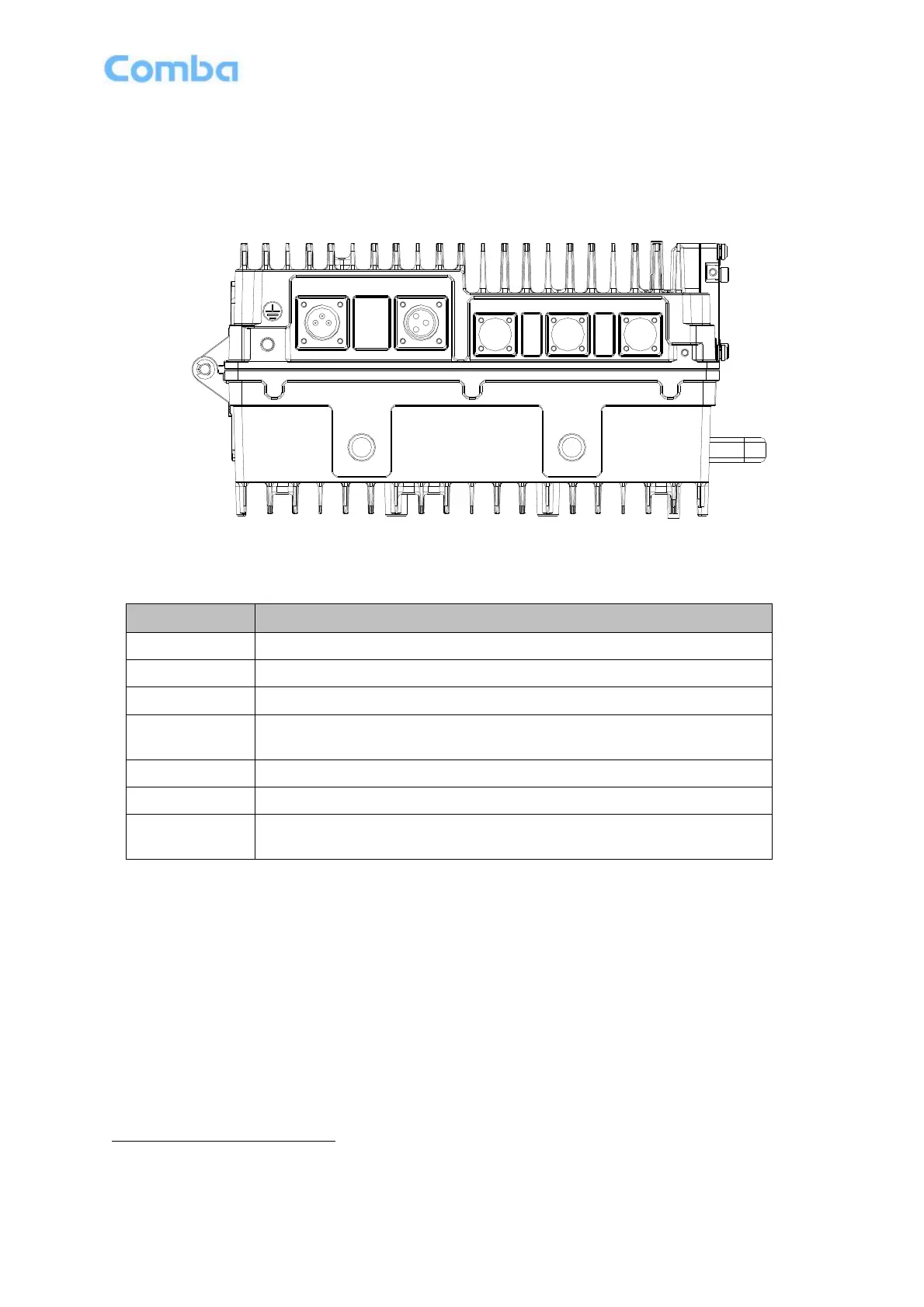
3.4 EQUIPMENT CONNECTORS
The RX-1839 is designed for all cable entries from the bottom of the enclosure, as shown in the following
figure.
DT
MT
MODEM ANT
EXT_ALM
RS-485
AC OUT
Power
Figure 7: Equipment Connectors
Table 2: Equipment Connectors
N-Female connector for connection to donor antenna
N-Female connector for connection to service antenna
7-pin CPC Connector for external alarm connection; RS485 for Slave unit
SMA-F Connector, for modem antenna connection. Slave unit has no
modem antenna port.
This is a power cable gland for a pre-installed power cord for connection to
AC or DC supply (e.g. 220/110V).
1
The voltage identification is a variant due to electricity system diversity of global regions. The power cable gland
might be identified for AC 220V, AC 110V, AC 220V/110V, DC -48V, or DC +24V respectively. Please refer to specific
product or contact local sales if any doubt.