4
1‐818‐841‐5500
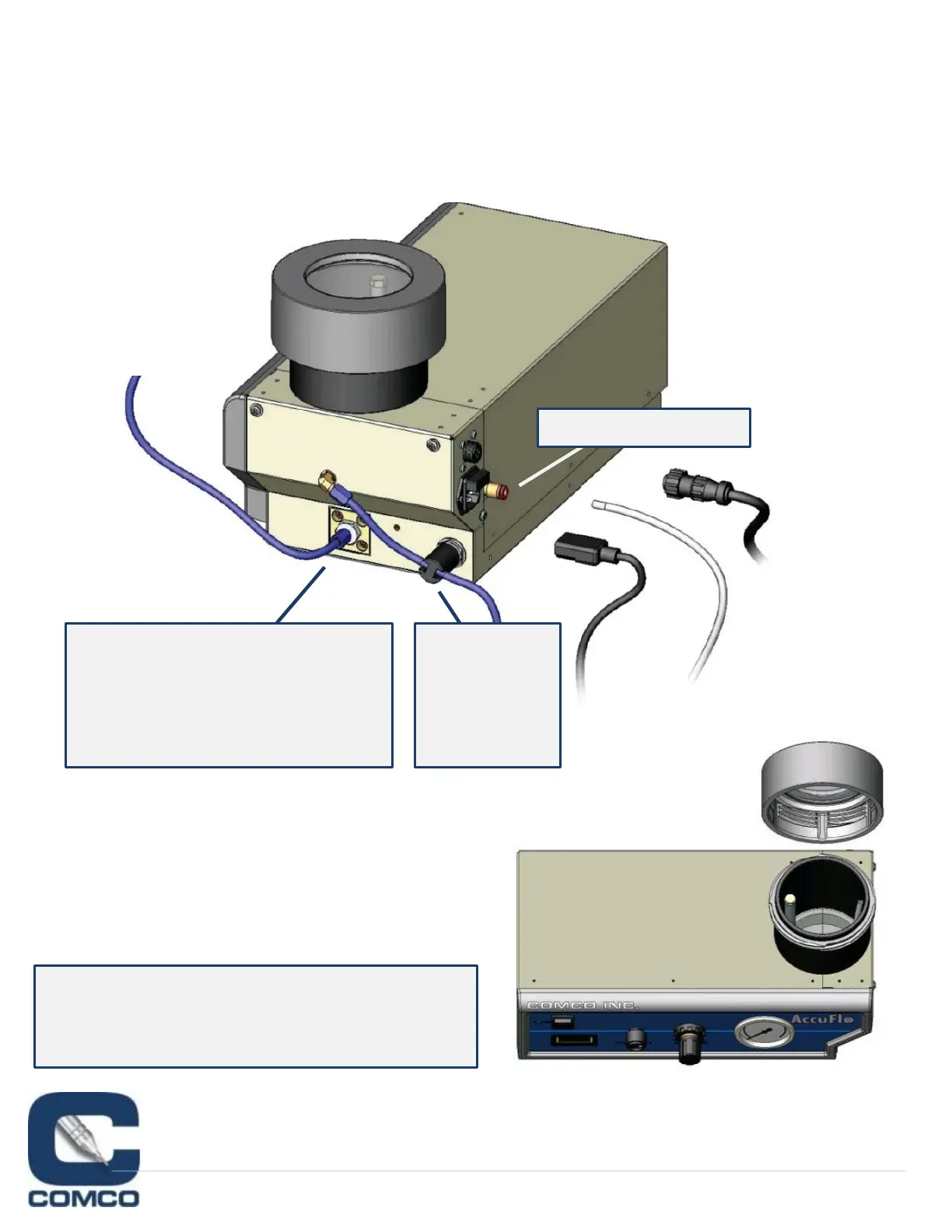
MakeConnections
1. PlacetheComfortGrip®handpiece insidetheworkchamber.
2. Placetheopenendoftheventhoseintothebackoftheworkstationorintothedustcollectorhose.
3. Connectthepowercordandtheblastcontrolcable.
4. Connecttheairsupplytothe“AirIn”fitting(using¼"tubingprovidedintheaccessorykit).
INLETAIRFITTING
THEABRASIVEHOSEFROMTHE
POWDERGATEVALVERUNS
DIRECTLYTOTHENOZZLE.
DONOTROUTETHISHOSE
THROUGHTHEVENTPINCH!
AddAbrasive
1. Removethetankcover.
2. Fillthetankwithpowder.Donotfillabovethe
topofbypasstube.
3. Replacethetankcoverandsecure(only¾turn
required).
VENTHOSE
ISROUTED
THROUGH
THEVENT
PINCH
TONOZZLE(S)
Alwaysmaintaina10psibufferbetweentheAccuFlo
pressuresettingandyourcompressor.Thisprotects
againstabrasiveflowingbackwardsthroughthe
machine.