EasyManua.ls Logo

Command access MLRK1 Series User Manual

Command access MLRK1 Series
4 pages
To Next Page IconTo Next Page
Page #1 background imageLoading...
Page #1 background image
INSERT INSTRUCTIONS
Visit our website for more details
www.commandaccess.com
Canada Customer Support
1-855-823-3002
U.S. Customer Support
1-888-622-2377
mlrk1-
A. 1- Motor Mount
B. 1- 40801 - Phillips head screw
C. 1- 50030 - 6’ Power Lead
D. 1- 50944 - molex pigtail
E. 2 - 40060 - Cable tie
F. 2 - 40059 - mounting pad
G. 1- 60368/51186 - remote mm4s module
H. 1 - 50741 - remote module cable
Kit Includes
Recommended Power Supplies: Use a power limited class 2 power supply
All Command Access exit devices & field installable kits have been thoroughly cycle tested with Command Access power
supplies at our factory. If you plan on using a non-Command power supply it must be a filtered & regulated linear power supply.
#20451_C
SPECIFICATIONS
SPDT - Rated .5a @24V
green= Common (C)
Blue = normally open (NO)
grey = normally closed (NC)
Optional built-in rex
Input Voltage: 24VDC +/- 10%
AVERAGE low Torque LATCH RETRACTION CURRENT: 900 mA
Average high torque latch retraction current: 2A
Average holding current: 215 ma
Wire gauge: Minimum 18 gauge
Direct wire run - no relays or access control units in-between power supply & module
A.
B.
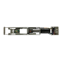
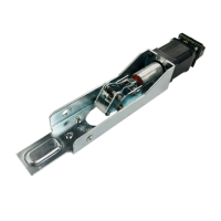
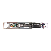
The Command Access MLRK1 is a Field-installable motorized latch-retraction kit:
• MLRK1-SGT - Sargent 80 series devices
• MLRK1-ARW - Arrow 1000 series devices
C.
INSTALLATION VIDEO
F. G.D. E.
H.

Other manuals for Command access MLRK1 Series

Questions and Answers:

Command access MLRK1 Series Specifications

General IconGeneral
TechnologyMicrowave Radar
Detection AreaAdjustable
Voltage12-24 VDC
Relay Output1x NO/NC, 5A 250V AC
Housing MaterialABS Plastic
Current Consumption<100mA
Operating Temperature-20°C to +55°C
Humidity0-95% non-condensing
Dimensions120mm

Summary

MLRK1- Kit Overview and Specifications

Kit Components

Lists all components included in the MLRK1 kit.

Technical Specifications

Technical specifications including voltage, current, and wire gauge requirements.

Optional REX Configuration

Details the optional Request-to-Exit (REX) feature wiring and color coding.

MLRK1- Setup and Troubleshooting

Setting the Push to Set (PTS) Adjustment

Explains the procedure for setting the Push to Set (PTS) adjustment for door conditions.

Troubleshooting and Diagnostics

Provides a guide to diagnose and resolve issues based on beep codes and system failures.

MLRK1- Installation Procedure

Initial Assembly and Bracket Connections

Details initial steps for disassembling the exit device and connecting motor components.

Housing Reassembly and Cable Routing

Guides on reassembling the exit device housing with the motor kit and securing components.

Final Connections and PTS Configuration

Details final wiring connections, module mounting, and the Push to Set adjustment process.

Related product manuals