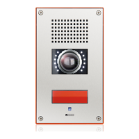
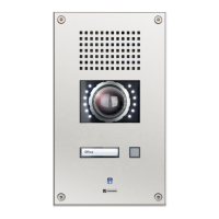
SIP station SIP-WS 201V CA
Connection diagram
approx. 1.65 m (5.4 ft)
Finished floor
160 (6.3)
140 (5.5)
275 (10.84)
255 (10.05)
4x Ø 7
(0.28)
Dimensions and recommended mounting height
Measuring units in mm (in), not to scale! Front panel thickness: 3 mm (0.12 in)
Extent of supply
• Station
• Mounting screws (4 x Torx TR 25 security
countersunk screws, M5 x 10)
• Snap-on ferrite (to be attached to IP uplink
Ethernet cable)
• Short reference
Cleaning instructions
Safety instructions
The device may only be cleaned with cleaning agents for stainless steel. Do not use cleaning agents
containing chlorine or isopropanol.
• This device may only be installed, replaced and maintained by trained and properly qualied
personnel (device class: ES1, PS2 as per IEC/EN 62368-1). The connectors are subject to possible
high transient voltage surges. The device is intended for appropriate installation in locations where
operating personnel cannot come into contact with uninsulated wires.
• Devices belonging to another earthing network must not be connected to the device’s connectors.
• Do not install the device on unstable walls or on surfaces which cannot support the device’s weight.
• Only accessories that comply with the device’s technical specications shall be used.
• All connected circuits shall full the requirements for ES1 (cf. SELV acc. IEC/EN 60950-1) and PS2
(Limited Power Source) as per IEC/EN 62368-1.
• Use shielded Ethernet cables only.
• Before using the device, ensure all cables are correctly connected and not damaged.
• Disconnect the power supply (PoE) for any maintenance of the device.
• Allow the device to cool down completely before touching parts inside.
• Do not make any unauthorised modications to the device.
expansion bus
OUT 2
OUT 2
OUT 2
OUT 2
OUT 1
OUT 1
MUTE
GND
LINE–
LINE+
IN 1
IN 2
IN 3
GND
factory
reset
button
external
loudspeaker module
handset
(e.g. WSHS 50P-JST)
EP+
EP–
EM+
EM–
IP downlink
(Axis camera
+ PoE)
IP uplink
+ PoE
LED brightness
+
–
slot for inserting
button label
1
2
Note:
It is recommended to keep the heating permanently ON to avoid condensation on the camera glass in
certain installation scenarios (e.g. inside metal columns). The same recommendation holds for envi-
ronments where the station is exposed to large uctuations in temperature and to high humidity.
Camera illumination and heating control
The camera illuminating and heating control are connected to the main board of the station
via the expansion bus. The web interface shows the two additional outputs.
Use OUT 1 on the EB2E2A as attendant contact to switch on the camera illuminator e.g. at call
setup
To dim the camera illuminator, use the potentiometer on the camera board.
Use OUT 2 on the EB2E2A as attendant contact to congure the camera’s heating (e.g. ON for
standby state).