11
COMMON S.A. CGT-OM-18 february.2018
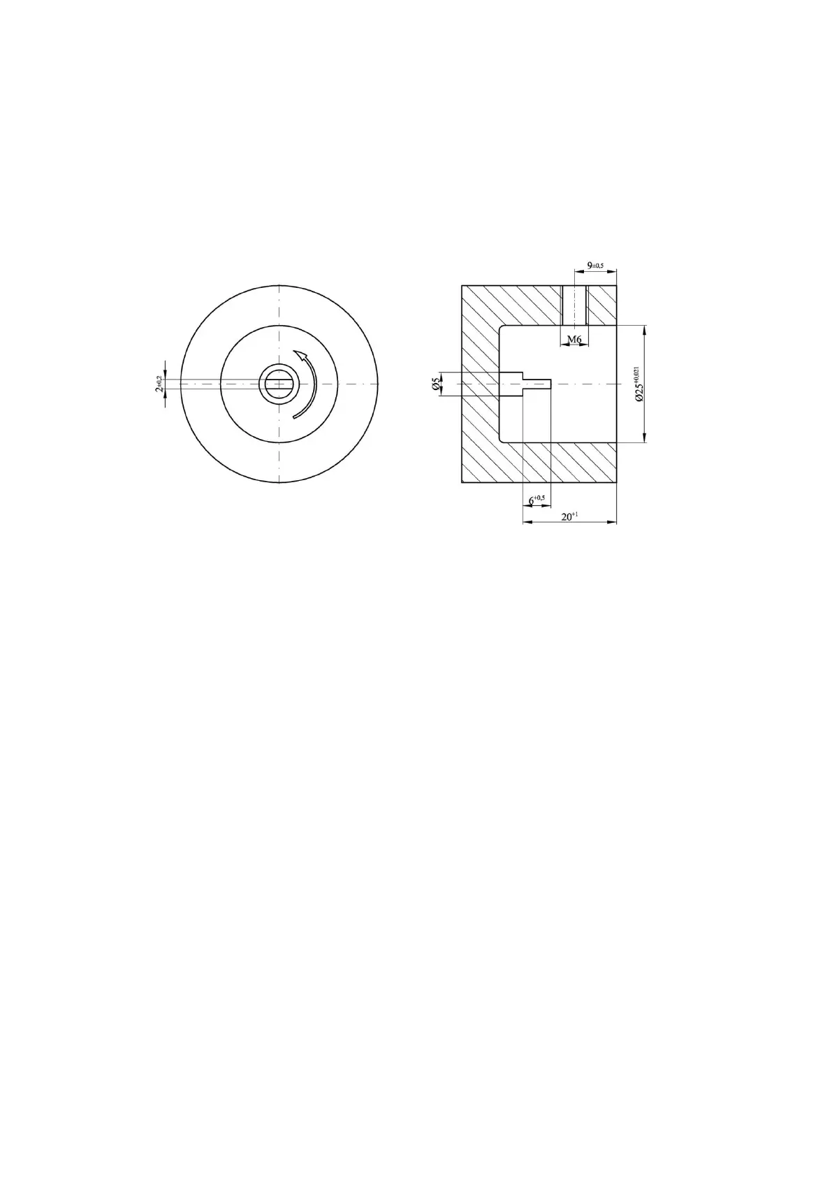
Mechanical counter output. The gas meter may be optionally equipped with a mechanical
output. A flattened tip of the counter shaft is located on the left side of the index head
and covered by a protective cap. The mechanical output may be used to drive external
devices. The rotational speed of the shaft is identical to the speed of the fastest counter drum.
The shaft rotates counter clockwise which is marked on the name plate located on the housing
of mechanical output (Fig. 11). There are also 2 other values specified on this name plate:
M
max
= 0,25
[Nmm] maximum permissible torque load on the shaft of the mechanical output,
and 1 tr = …… [m
3
] value of the constant corresponding to one rotation of the shaft.
Fig. 4. Mechanical output dimensions
Electrical counter outputs. There are two possible types of electric signal outputs:
low frequency (LF) outputs and high frequency (HF) outputs. The index head can be equipped
with one or two 6-pins sockets. Up to three electric pulse emitters can be connected to each
of the sockets. The pulse emitters are:
- one or two inductive high frequency emitters HF,
- one or two inductive low frequency emitters LFI,
- one or two low frequency reed contact emitters LFK,
- one or two low frequency emitters LFW equipped with Wiegand sensor
- one control circuit utilising normally closed reed relay switch AFK.
The reed relay emitters LFK and LFW are designed to work with a battery-powered
or grid/battery-powered data logger and volume converter located in the vicinity of the gas
meter (up to ca. 2 m). The induction emitters, both of the LFI and the HF type, may emit
electric current signals over significantly longer distances (up to ca. 200 m, depending
on conditions). Due to high power consumption, they are designed to work only with grid-
powered volume converters. Gas volumes corresponding to individual pulses of the LF
emitter are presented in Table 2.
The number of HF pulses per one cubic meter of gas is determined individually for each gas
meter and listed on the type plate.
All emitters located in the gas meter index head are connected to Tuchel C091 31N006 100 2
or Lumberg Connect 0304 06 sockets located in the back wall of the index. Cords connected
to sockets should be equipped with Tuchel C091 31H006 100 2 or Lumberg 0332 06 plugs.
Tuchel connections in CGT-02 gas meters are of the IP67 protection class. Table 3 presents
possible connections of emitters to individual electric signal output sockets.
 Loading...