10
D2 – with lever, p
max
≤ 6.3 [MPa], DN200, DN250, DN300, DN400,
D3 – with lever, 6.3 [ MPa] < p
max
≤ 11 [MPa], DN200, DN250, DN300, DN400.
Typical DN50 gas meters are not adapted for external lubrication. These meters can be
optionally equipped with piston pump or lubrication valve.
A sticker is attached to the oil container cover, providing information about the type
of the pump used and the type of oil which should be used. Information about the type of oil
is also provided on the lubrication valve cover.
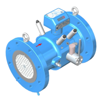
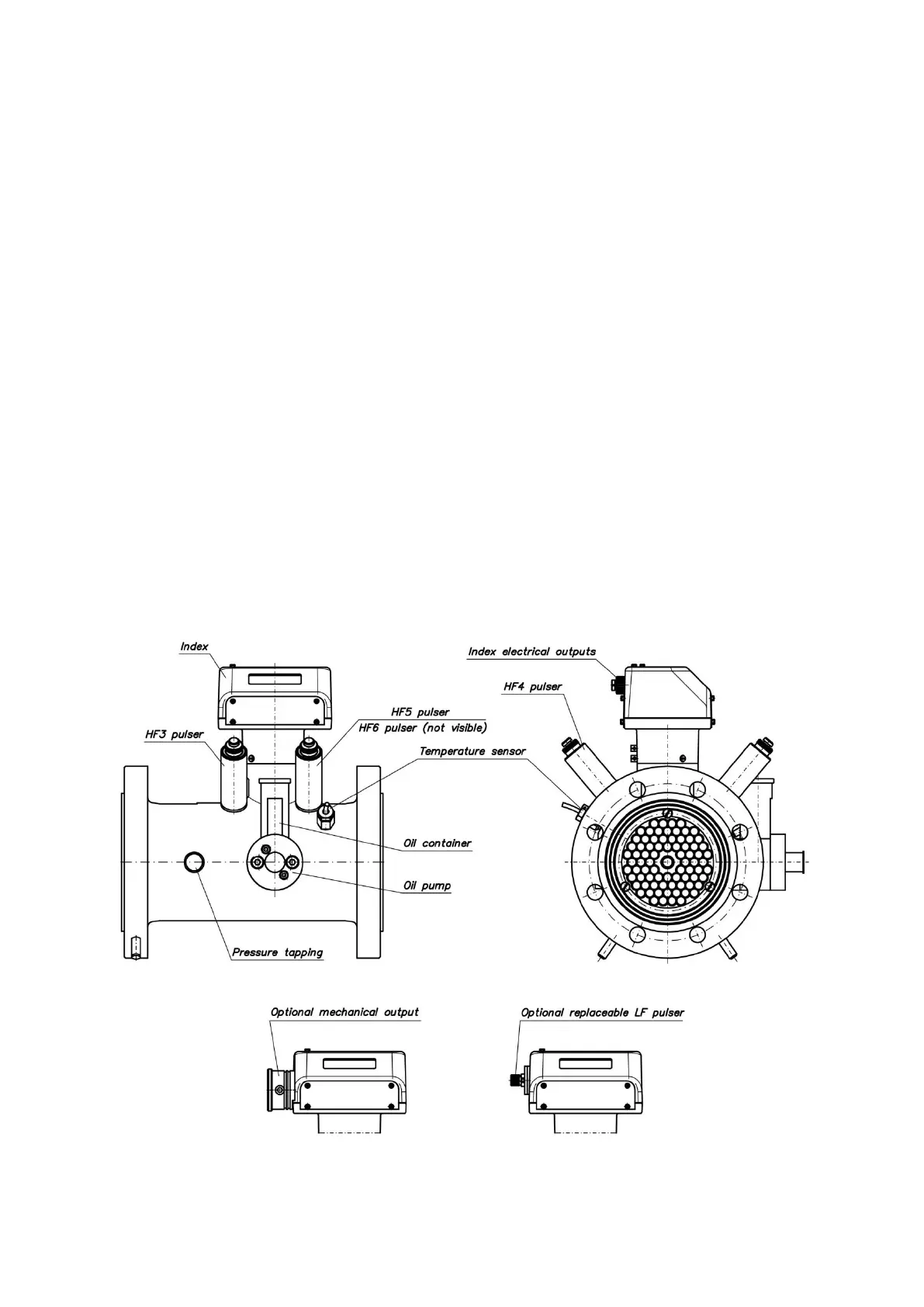
III. READOUT DEVICE AND MEASUREMENT OUTPUTS
The gas meter CGT-02 is equipped with a readout device in the form of a mechanical
counter with electric signal outputs. The body of the gas meter is equipped with sockets
for implementation of external HF emitters and sockets for the (optional) measurement
of pressure and temperature. Such measurements enable monitoring the gas meter operation
and connecting to the external equipment. Fig. 3 shows the location of the measurement
outputs of the gas meter.
The mechanical counter is located inside the index head assembly and visible through
a polycarbonate inspection window. The counter allows direct readout of the actual volume
of gas that has flown through the gas meter under particular pressure and temperature
conditions. The index assembly may be rotated around its axis in a range of ca. 350
o
, allowing
for convenient readout of the counter from virtually all directions.
Fig. 3. Location of measurement outputs of CGT-02 gas meters.
 Loading...