12
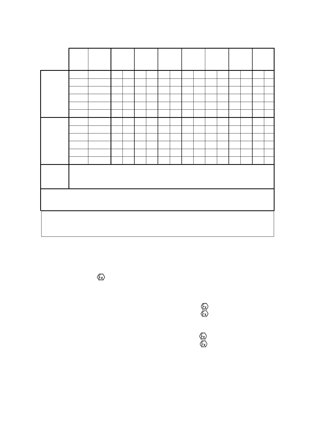
Table 3. Possible connections of gas meter emitters to index output sockets
S – standard connections, P – preferred connections, O – optional connections
(*) – not available with replacaeable LF sensors
The view and numbering of the pins Sockets 1 and 2 is shown in Figure 9a (9b).
Standard versions of the CGT-02 gas meter features only one
low frequency reed contact emitter LFK 1
In the case where two sockets in the index head are used as an output for the sensor's circuits, the
cables connected to those sockets should be marked with tags indicating the socket number to which
the specified cable should be connected.
One of the inductive emitters HF3 to HF6 installed in the gas meter body may act as a control
element in the CGT-02 meter. The constants for emitters HF3-HF6 are listed on the type
plate.
In line with the conditions of use, the CGT-02 gas meters should be equipped with emitters
allowing for at least II 2G Ex ib IIC T5 Gb protection. This condition is satisfied
for instance by the following emitters used in the index:
- HF type Bi1-EG05-Y1
(1)
by Hans Turck GmbH
Certificate No. IECEx KEM 06.0036X marking Ex ia IIC T4... T6
Certificate No. KEMA 02ATEX1090X marking II 1G Ex ia IIC T4...T6 or
II 2G Ex ia IIC T4...T6
- LFI type Si5-K09-Y1
(1)
by Hans Turck GmbH
Certificate No. IECEx KEM 06.0036X marking Ex ia IIC T4... T6
Certificate No. KEMA 02ATEX1090X marking II 1G Ex ia IIC T4...T6 or
II 2G Ex ia IIC T4...T6
- LFK type CLFK-03 by Common S.A.
- LFW type CLFW-01 by Common S.A.
- LFW type CLFW-02 by Common S.A.
(1) – required linear characteristics of the emitter power circuit.
 Loading...