13
COMMON S.A. CGT-OM-18 february.2018
Acceptable intrinsic safety parameters
ATTENTION!
The total voltage of separate galvanic intrinsically safe circuits connected
to one connector must comply with: Ui1 + Ui2 ≤ 30 V
Intrinsic safety parameters of the emitters installed in the gas meter are listed
on the type plate.
The security level is also met by the following interchangeable transmitters:
- LFK type CLFK-04 manufactured by Common S.A.
- LFW type CLFW-04 manufactured by Common S.A.
Acceptable intrinsic safety parameters
Electrical outputs for HF emitter signals in the gas meter body.
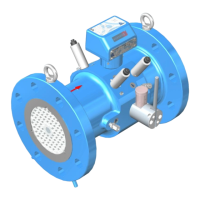
The high frequency pulse emitters may be placed in the main body of the gas meter
over the turbine rotor or over the reference wheel (option), which features the number of cogs
equal to the number of turbine blades. In such case, the magnetic field of the HF emitter
is modulated by the turbine rotor or the reference wheel giving the same pulse rate.
The HF emitters can be installed as shown in Fig. 3. The sockets feature a M16 x 1.5 thread
(Fig. 5).
Installation of the HF emitter in the gas meter body requires high precision and the use
of electronic control equipment and such must be performed only by a representative
of the manufacturer or a company authorized by the manufacturer.
Maximum of four near field inductive high frequency emitters (HF) may be installed
in the gas meter:
- one or two HF emitters over the turbine rotor,
- one or two HF emitters over the optional reference wheel.
 Loading...