14
The emitters should allow for at least 2G Ex ib IIC T5 Gb protection. These conditions
are satisfied, for example, by the following emitters:
- CHFI-01 by Common S.A., equipped with Bi1-EG05-Y1
(1)
sensors (Hans Turck
GmbH: Certificate No.: IECEx KEM 06.0036X, marking Ex ia IIC T4...T6 and
Certificate No.: KEMA 02ATEX1090X marking II 1G Ex ia IIC T4...T6 or
II 2G Ex ia IIC T4...T6)
- CHFI-03 by Common S.A., equipped with Bi3-EG12-RY1/S1000
(1)
sensors
(Hans Turck GmbH, Certificate No.: KEMA 02ATEX1152X
marking II 1G Ex ia IIC T4...T6 or II 2G Ex ia IIC T4...T6)
(1) – required linear characteristics of the emitter power circuit.
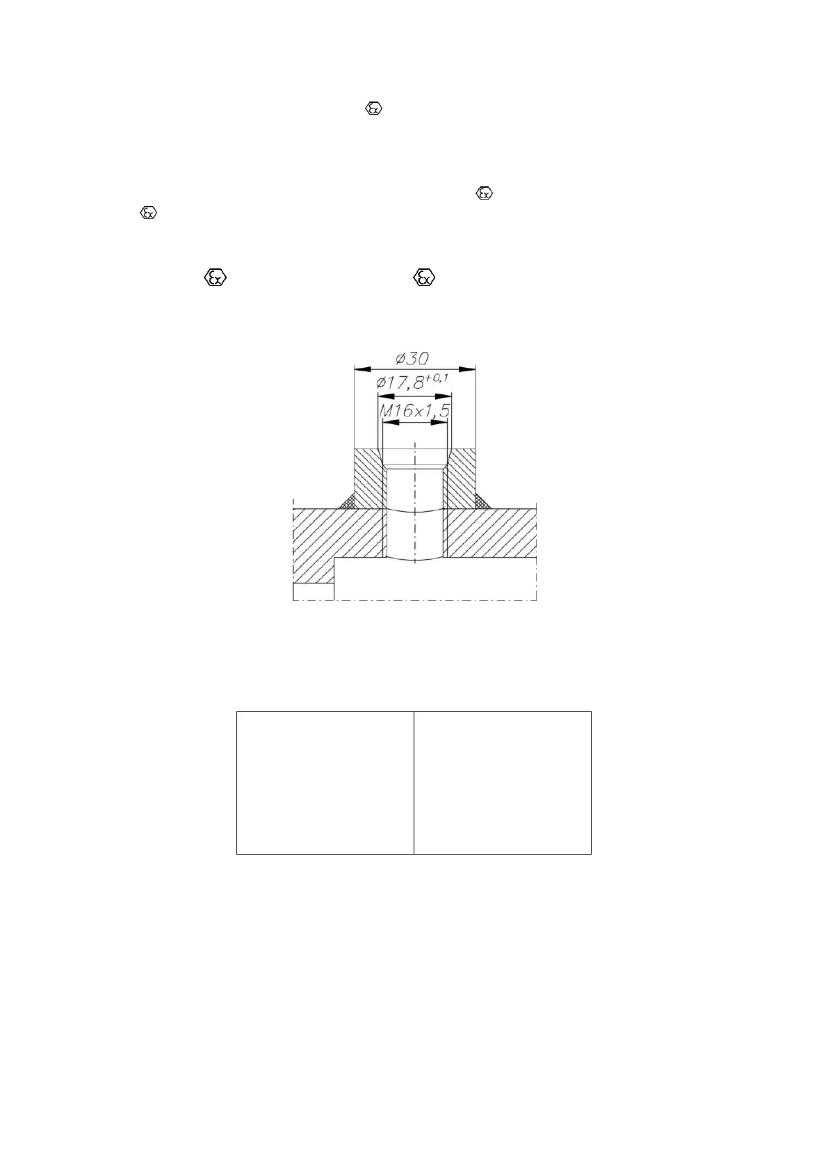
Fig. 5. Dimensions of the sockets for the HF pulse emitters.
Acceptable intrinsic safety parameters:
Intrinsic safety parameters are listed in the type plate located at the emitter casing
(Fig. 10).
The emitters are equipped with 4-pin Tuchel C091 31W004 100 2 connectors. They should be
connected to cords with Tuchel C091 31D004 100 2 slots. The emitter is connected to pins
3 and 4. Figure 6 presents a diagram of the connection of the emitter to the measurement
circuit.
 Loading...