15
COMMON S.A. CGT-OM-18 february.2018
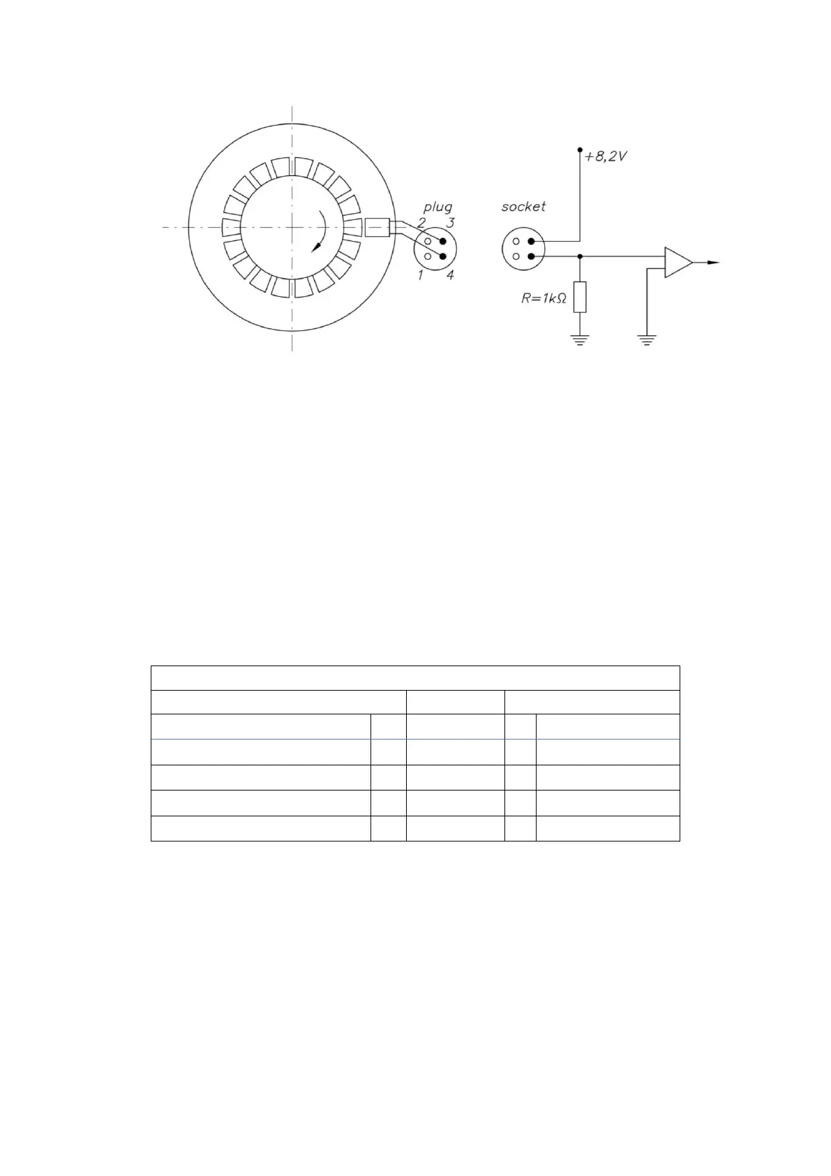
Fig. 6. Diagram of the HF emitter connection
The number of HF pulses per one square meter of gas is determined individually for each
gas meter and listed on the electrical outlets type plate. (Figs. 9 and 10), placed at the top
of the index head.
NOTE!
Intrinsic safety parameters are electrical parameters designated during analysis of
construction of intrinsically safe device. Their values are determined for the most unfavorable
state of work or damage to the device. The values of these parameters are limited to the levels
that are safe for the given explosive mixture. They should not be treated as technical
parameters of the device's operation.
The conditions for compliance of the intrinsic safety parameters of connected devices
are presented in the table below.
Conformity conditions for intrinsic safety parameters
Connected external device
Maximum external capacity
Maximum external inductance
The distributed parameters of cables (Ck), (Lk) should be taken as:
The least favorable parameters given by the cable manufacturer or
Parameters measured in accordance to EN 60079-14 or 200pF/m & 1H/m or
30H/ where the connection consists of 2 or 3 wires (with or without shield)
Rated operating parameters of used transmitters:
LFK transmitters – reed contact and LFW with output type „open collector”
CLFK-03 / CLFK-04 / CLFW-01 / CLFW-02 / CLFW-04
Closed contact resistance R
z
= 100 ÷ 2 k ,
Open contact resistance R
o
> 100 M ,
 Loading...