16
Maximum switching frequency f
p
= 2 Hz .
Inductive slot transmitters and inductive proximity transmitters in NAMUR standard.
Si5-K09-Y1 Bi1-EG05-Y1
CHFI-01, CHFI-03
Maximum switching frequency f
p
= 2 Hz, f
p
= 0,5 kHz.
Rated operating voltage Un = 8,2V
Rated current of the non-activated sensor I >= 2,1mA
Rated current of the energized sensor I <= 1,2mA
Other rated operating parameters of the transmitters are in accordance with the
requirements of PN-EN 60947-5-6: 2002.
When connecting transmitters to inputs of pulse receiving devices, the polarity of conductors
should be maintained. Only LFK and AFK transmitters do not require polarization.
The HF outputs are particularly useful for recording fluctuations and rapid changes of the gas
flow.
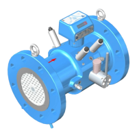
Pressure measurement outputs.
Pressure measurement outputs are located on both sides of the main body of the meter
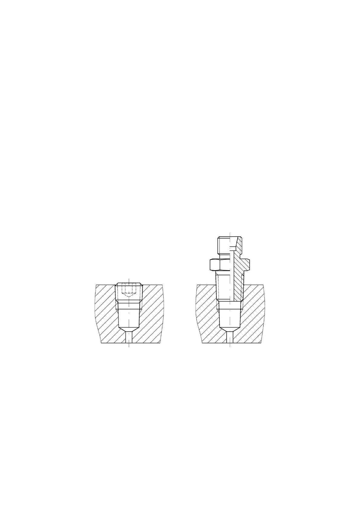
(Fig. 3). They are machined as ¼ NPT taper threads (Fig. 7).
a.) b.)
Fig. 7. ¼ NPT pressure measurement output
The outputs are adjusted to connecting pressure transducers, either directly to the socket
or through impulse lines and three-way valves (impulse line connector, Fig. 7b). Outputs
that are not in use are closed with plugs (Fig. 7a). Both plugs and sockets may be secured
with installation seals.
 Loading...