EasyManuals Logo

Common CGT-02 Series User Manual

Common CGT-02 Series
42 pages
To Next Page IconTo Next Page
To Previous Page IconTo Previous Page
Page #32 background imageLoading...
Page #32 background image
32
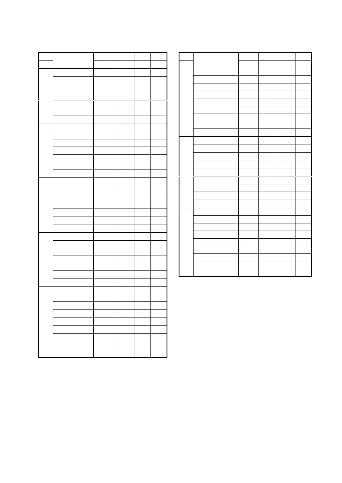
Table 3b. Dimensions of the connections of CGT-02 turbine meters (DN50÷DN400).
DN
connection
(flange)
DZ
D0
d0
n
mm
mm
mm
mm
qty
50
PN10/16
165
125
18
4
PN20/ANSI150
150
120.5
18
4
PN25/40
165
125
18
4
PN50/ANSI300
165
127
18
8
PN63
180
135
22
4
PN100
195
145
26
4
PN110/ANSI600
165
127
18
8
80
PN10/16
200
160
18
8
PN20/ANSI150
190
152.5
18
4
PN25/40
200
160
18
8
PN50/ANSI300
210
168.5
22
8
PN63
215
170
22
8
PN100
230
180
26
8
PN110/ANSI600
210
168.5
22
8
100
PN10/16
220
180
18
8
PN20/ANSI150
230
190.5
18
4
PN25/40
235
190
22
8
PN50/ANSI300
255
200
22
8
PN63
250
200
26
8
PN100
265
210
30
8
PN110/ANSI600
275
216
26
8
150
PN10/16
285
240
22
8
PN20/ANSI150
280
241.5
22
8
PN25/40
300
250
26
8
PN50/ANSI300
320
270
22
12
PN63
345
280
33
8
PN100
355
290
33
12
PN110/ANSI600
355
292
29.5
12
200
PN10
340
295
22
8
PN16
340
295
22
12
PN20/ANSI150
345
298.5
22
8
PN25
360
310
26
12
PN40
375
320
30
12
PN50/ANSI300
380
330
26
12
PN63
415
345
36
12
PN100
430
360
36
12
PN110/ANSI600
420
349
32.5
12
DN
connection
(flange)
DZ
D0
d0
n
mm
mm
mm
mm
qty
250
PN10
395
350
22
12
PN16
405
355
26
12
PN20/ANSI150
405
362
26
12
PN25
425
370
30
12
PN40
450
385
33
12
PN50/ANSI300
445
387.5
29.5
16
PN63
470
400
36
12
PN100
505
430
39
12
PN110/ANSI600
510
432
35.5
16
300
PN10
445
400
22
12
PN16
460
410
26
12
PN20/ANSI150
485
432
26
12
PN25
485
430
30
16
PN40
515
450
33
16
PN50/ANSI300
520
451
32.5
16
PN63
530
460
36
16
PN100
585
500
42
16
PN110/ANSI600
560
489
35.5
20
400
PN10
565
515
26
16
PN16
580
525
29.5
16
PN20/ANSI150
600
540
29.5
16
PN25
620
550
36
16
PN40
660
582
39
16
PN50/ANSI300
650
571.5
35.5
20
PN63
670
585
42
16
PN100
715
620
48
16
PN110/ANSI600
685
603
42
20
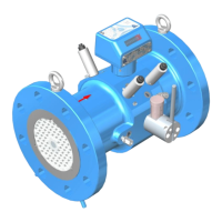
Impurities inside a pipeline system carried by gas may cause mechanical damage to the gas
meter or at least reduce its measurement accuracy. Therefore, a filter with efficacy not worse
than 10 m should be installed upstream the gas meter (particularly when the flowing gas
contains high amounts of impurities). In addition, the inflow side of the system should be
thoroughly cleaned before installing the gas meter. Conical sack filter may be placed
on the inlet of the inflow section; the filter should be removed after 1 2 months of operation.
If the filter is not removed, monitoring of the filter impurity level should be provided
by means of pressure drop measurements or regular check-ups. If clogged, the sack filter may
be destroyed by the gas pressure, and filter debris may seriously damage the gas meter.
Table 3b. Basic dimensions and weights of CGT-02 turbine gas meters in the DN400÷DN600
size range
Table 3b. Basic dimensions and weights of CGT-02 turbine gas meters in the DN400÷DN600
size range

Questions and Answers:

Question and Answer IconNeed help?

Do you have a question about the Common CGT-02 Series and is the answer not in the manual?

Common CGT-02 Series Specifications

General IconGeneral
BrandCommon
ModelCGT-02 Series
CategoryMeasuring Instruments
LanguageEnglish