33
COMMON S.A. CGT-OM-18 february.2018
The manufacturer is not responsible for any damages or stoppage of the gas
meter resulting from insufficient filtration of the gas flowing through the meter.
The user should be aware of certain risks associated with changes in the gas flow intensity.
If the gas flow was relatively low for a long time after system initiation, the assembly-related
contaminants (e.g. welding residues) are retained inside the pipework. Only after the flow
is significantly increased, the contaminants may be swept away by the gas, causing gas meter
damage. For this reason, the sack filter may prove useful in the period of time when
maximum system capacity is being reached. In all cases, protection of the gas meter
from mechanical damage is in the user's best interest.
Before completion of the installation of the gas meter ensure it is properly oriented, i.e. that
the arrow on the meter body points in the direction of the gas flow.
The gas meter should be connected to pipework flanges by means of bolts meeting
the requirements of the EN 1515-1, EN 1515-2, EN ISO 898-1, and ISO 898-1 standards.
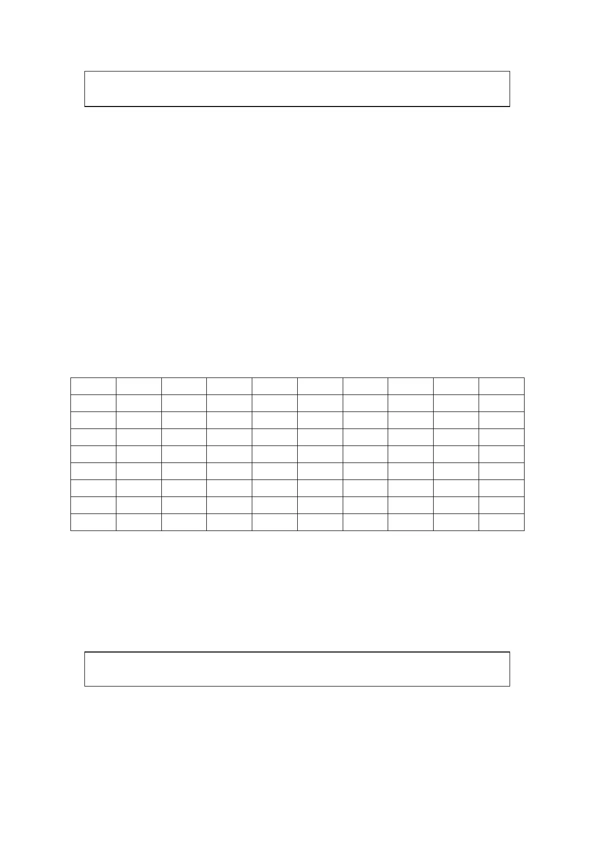
To make the selection of bolts easier, table 4 lists the minimum required yield strength values
for materials of bolts used for flange connections for CGT-02 gas meters.
Table 4. Minimum yield strength for bolt materials R
e
[MPa].
Appropriate flange gaskets should also be selected for specific flange types and nominal
pressures. Flange connections should be sealed with gaskets made of asbestos-free gasket
sheet. Flat gaskets can be used for standard flanges with type “B” facings and p
max
= 2 MPa
(according to EN 1514-1:1997 or EN 12560-1:2001), while meters for p
max
> 2 MPa require
corrugated gaskets (according to EN 1514-4:1997 or EN 12560-4:2001.
Appropriate bolt lengths should be selected with consideration to dimensions
listed in Tables 3a and 3b and the thickness of gaskets being used.
Tables 5a and 5b list the required tightening bolt torque values for flange connections.
 Loading...