4. Commissioning
Page 18 MF0150A9A_prel.docx Manual for ION-M23 SDARS 3-Sector
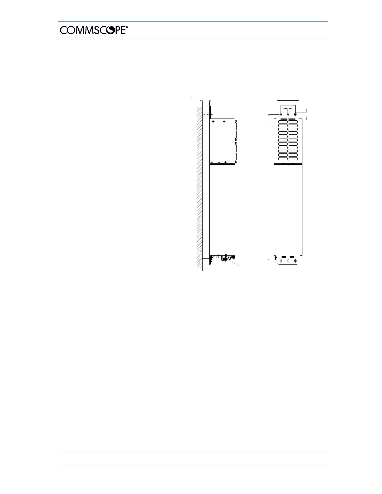
4.1.3. Wall-Mounting Procedure
Check the suitability of the wall-mounting kit and the wall.
Mark the position of the drilling
holes (for measurements refer to
figure 4-1 Wall mounting). Drill four
holes at the marked positions and
insert dowels *.
Use a cap nut or lock nut to screw
the four dowel screws into the
dowels and put the distance tubes
over the screws.
Hang the mounting brackets of the
Remote Unit into the screws, and
fasten them immediately using the
washers and nuts.
Ensure that there is free access to
the electrical connections as well
as to the cabinet. The approved
bending radius of the connected
cables must not be exceeded.
figure 4-1 Wall mounting, (metric dimensions)
* The dowels are not part of the delivery since the suitable type depends on the on-site conditions
(material of wall). Therefore, use dowels that are appropriate for the mounting surface.
Wall mounting with active cooling kit
4.0 0.50
4
Mains supply
9
80 ± 0.50
122 ± 0.50
18
796 ± 1.00
G0946Z0