5. System Operation
PowerShift User Manual Version B Page 11
Figure 5-2 LED Status Indicators
b. LEDs 1, 2 and 3 provides the individual status of each of the three power
circuits in the module
c. LED X represents the status of the overall module
d. Intermittent or latent failures will be indicated by the LED X indicator, even
if the individual circuit LEDs are functioning correctly
e. See the alarm table in the next section for additional details
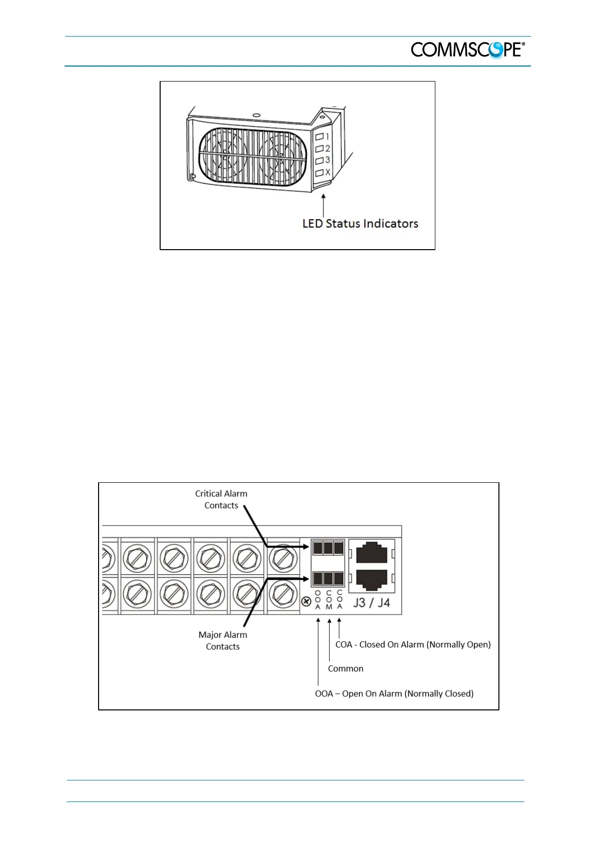
5.3. Form C Alarm Dry Contacts
As shown below, the alarm status of the unit is externally accessible with the terminal
block located at the rear of the unit, on the far right.
Figure 5-3 Alarm Relay Connections