5. System Operation
PowerShift User Manual Version B Page 9
5. System Operation
5.1. General Operating Description
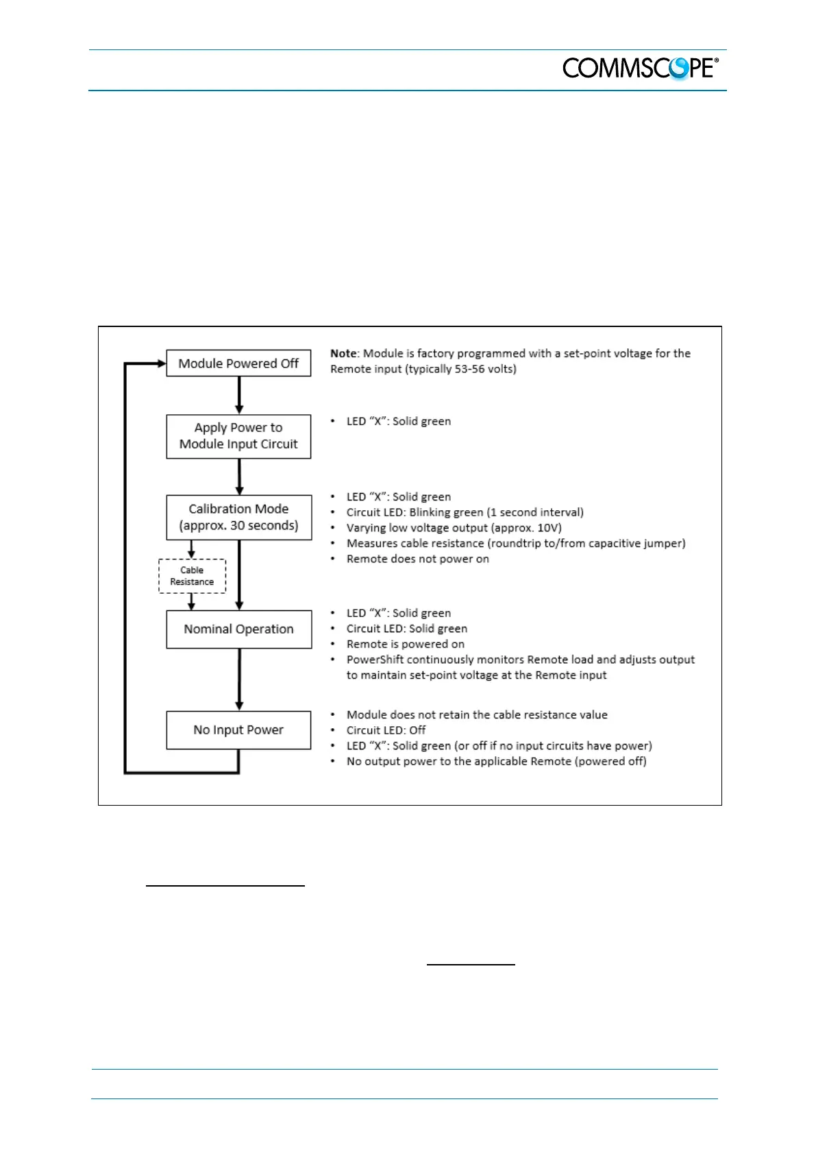
The diagram below provides a basic operating description of an installed
PowerShift system.
Note that each Base Unit module has three circuits, and each circuit has its
own input and output terminals; the three circuits operate independently from
one another.
Figure 4-1 Operating Description
Operating Description
a. The module is programmed at the factory with a set-point voltage for the
Remote input (typically 53-56 volts)
b. Whenever input power is active on one or more of the three circuits, the
module “X” LED will be solid green
• A red or yellow LED indicates a fault at the module level; see the next
section for more information