4. Introduction
PowerShift User Manual Version B Page 7
PowerShift Base Unit
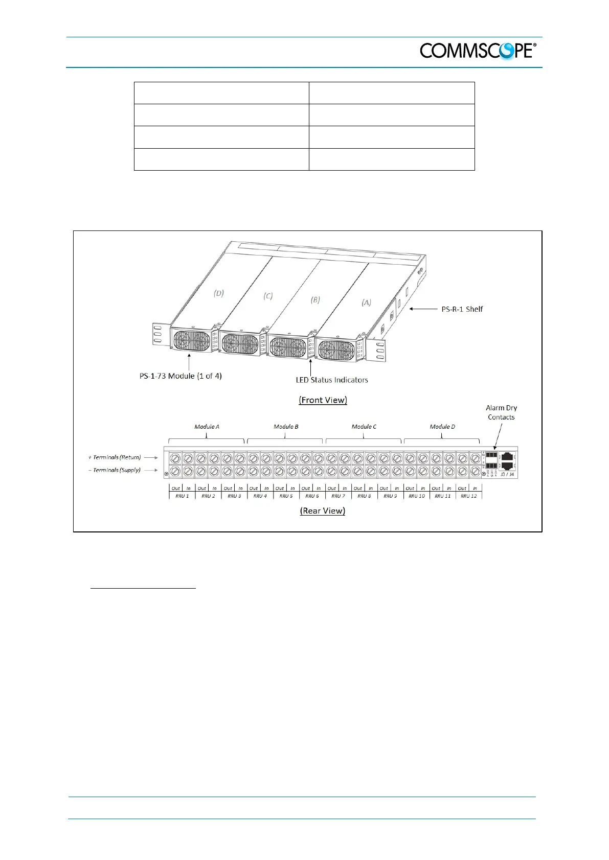
Figure 4-1 PowerShift Base Unit
Base Unit Features
• The Base Unit is typically collocated with the existing DC power plant (e.g.,
installed in or near the DC power plant cabinet)
• The Base Unit is comprised of the PS-R-1 shelf and PS-1-73 power modules
• The modules are plug-and-play for easy installation and site maintenance
• Each module has three individual DC input and DC output circuits that provide
power for three Remotes (radios)
• The shelf accepts four modules, providing a total capacity for 12 Remotes
• The shelf has dry-contacts (Form C) for remote alarm monitoring
• Each module has LED indicators that provide status information: The “X” LED
at the bottom provides overall status for the module, and the LEDs “1”, “2” and
“3” provide status for each individual circuit