R550 Access Point
Quick Setup Guide
This Quick Setup Guide pr
ovides step-by-step instrucons on how to install
and begin using your Ruckus R550 dual-band 802.11ax indoor Wi-Fi access
point (AP).
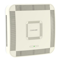
FIGURE 1 R550 Access Point: Top View
This Guide in Other Languages
• 请从以下网站获得该指南的简体中文版 hps://
support.ruckus
wireless.com.
• Vous trouverez la version française de ce guide à l'adresse suivante
hps://support.ruckuswireless.com.
• このガイドの日本語版は hps://support.ruckuswireless.com でご覧
ください。
• 이 가이드의 한국어 버전은 웹 사이트 (hps://
support.ruckuswireless.com) 에서 확인하시기 바랍니다.
• Veja a versão em português (Brasil) deste guia em hps://
support.ruckuswireless.com.
• Puede ver la versión en español (América Lana) de esta guía en
hps://support.ruckuswireless.com.
Before You Begin
Before deploying Ruckus products, please check for the latest soware and
the release documentaon.
• Release Notes and other user document
aon are available at hp://
support.ruckuswireless.com/documents.
• Soware upgrades are available at hp://support.ruckuswireless.com/
soware.
• Soware license and limited warranty informaon are available at
hp://support.ruckuswireless.com/warranty.
NOTE: The minimum soware versions for the R550 AP are:
• SmartZone (SZ) 5.2 New AP Model Patch
• ZoneDirector (ZD) 10.4.1 Nave Support
Package Contents
A complete R550 installaon package includes all of the following items:
• R550 Access Point
• One wall-mount anchor kit, including two 1-inch No. 8 steel pan-head
Phillips sheet metal screws and wall-mount anchors
• One external T-bar bracket (two unassembled parts)
• Service Level Agreement/Limited Warranty Statement
• Declaraon of Conformity
• Regulatory Statement
• Ruckus Access Point Geng Started Guide
• AP Cloud Management Insert
• This Quick Setup Guide
Required Hardware Tools
• Admin PC (computer with an Ethernet port and Wi-Fi adapter)
• Cat 5e (or beer) Ethernet cable
• Ruckus Wireless 12 VDC power adapter (sold separately) or
802.3at-compliant Power over Ethernet (PoE) switch or PoE injector
Oponal hardware and tools:
Customer-ordered Ruckus Wireless 902-0120-0000 secure mounng
bracket kit:
• If you are mounng the AP on a at surface using the secure mounng
bracket kit, then you need an electric drill with 4.75-mm (3/16-in.) drill
bits.
• If you are mounng the AP on a pipe or pole using the secure mounng
bracket kit, then you will also need a 38.1-mm to 63.5-mm (1.5-in. to
2.5-in.) pipe or pole, customer-supplied two pole clamps, and hand
tools to ghten the clamps.
Step 1: Connecng Your Computer to the AP
1. Using an Ethernet cable, connect your computer network port to the
PoE port on the AP. Refer to Figure 2.
2. Connect the AC cable of the AC power adapter to a convenient and
protected power source. Connect the DC output cable of the AC
power adapter to the 12 VDC port on the AP.
NOTE: Alternavely, connect the PoE port to a PoE injector or
switch for both power and network connecvity.
Alternavely, connect the computer and the AP with a basic PoE
switch in the following ways:
a) Connect the AP to a switch port.
b) Connect the computer to another switch port and manually
assign an IP address to congure the AP.
FIGURE 2 R550 AP Ports on Boom Panel
TABLE 1 R550 AP Ports
No. Label Descripon
1
1G ETH 10/100/1000 Mbps port: RJ-45 Ethernet
port (non-PoE)
2 PoE 10/100/1000 Mbps PoE In Port: RJ-45
Ethernet port (supports 802.3af/at PoE)
3 12 VDC 12 VDC input
4 USB USB Port
• Maximum Dimensions: 6 cm x 2 cm x
1.1 cm
• Interface: USB 2.0
• Connector: USB – Type-A plug
5 Reset
switch
Resets the AP
3. Verify that the PWR LED on the AP is lit a steady green.
Step 2: Preparing Y
our Computer for AP Setup
NOTE: The following procedures assume Windows is the operang
s
ystem. Procedures for other operang systems are similar.
1. On your Windows PC, navigate to Start > Con
trol Panel > Network
and Sharing Center > Change Adapter Sengs to congure your
network adapter from the Local Area Connecon sengs.
2. Navigate to Local Area Connecon > Properes > Internet Protocol
Version 4 (TCP/IPv4) > Properes to edit the TCP/IPv4 address
sengs.
The Internet Protocol Version 4 (TCP/IPv4) Properes dialog box
displays.
Copyright
©
2020 CommScope, Inc. All rights r
eserved. Page 1 of 4
Published March 2020, Part Number 800-72433-001 Rev A
Ruckus Wireless Inc.
350 W. Java Dr., Sunnyvale CA 94089 USA
Contact us at www.ruckuswireless.com