The nozzle switch leads plug in between 'NSWx' and 'GND' (see Figure 10
above). When the nozzle is lifted, the nozzles switch closes and the C4000
initiates a transaction.
Diagnostic LED will flash rapidly when any nozzle is lifted
regardless of hose configuration.
The Sump Switch is a float switch located in a sump at the bottom of the
dispenser. If the dispenser pipe work leaks, then the tray fills with product,
thereby activating the switch.
If the switch closes, then the dispenser stops and the litres display reads
"SunP".
The Sump Switch is wired into the SUMP and GNS terminals on the J12
connector (see Figure 10). If there is more than one head in the dispenser
(e.g. MHD6), then the sump switch is to be connected to both heads.
Ensure that the SUMP terminals are joined and the GNS terminals are
joined.
DO NOT connect the GNS terminal on one head to the
SUMP terminal on the other.
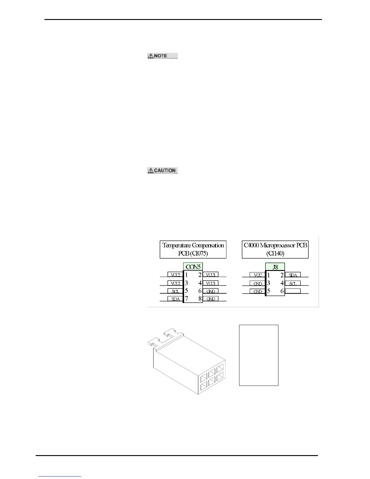
The Temperature Compensation PCB is mounted in a separate enclosure
and is connected to the C4000 Microprocessor via a four wire cable. The
PCB Pin headers and cable connectors are shown below.