Compaq.com - Compaq Presario Maintenance and Service Guide - 5200 Series
United States December 10, 2002
Maintenance and Service Guide
Compaq Presario 5000, 5100, and 5200 Series Computers
MSG index Product Description Troubleshooting Illustrated Parts Catalog
Home Removal & Replacement Jumper & Switch Information Specifications
System
boards
Hard drives
DVD drive
CD drive
Zip drive
l
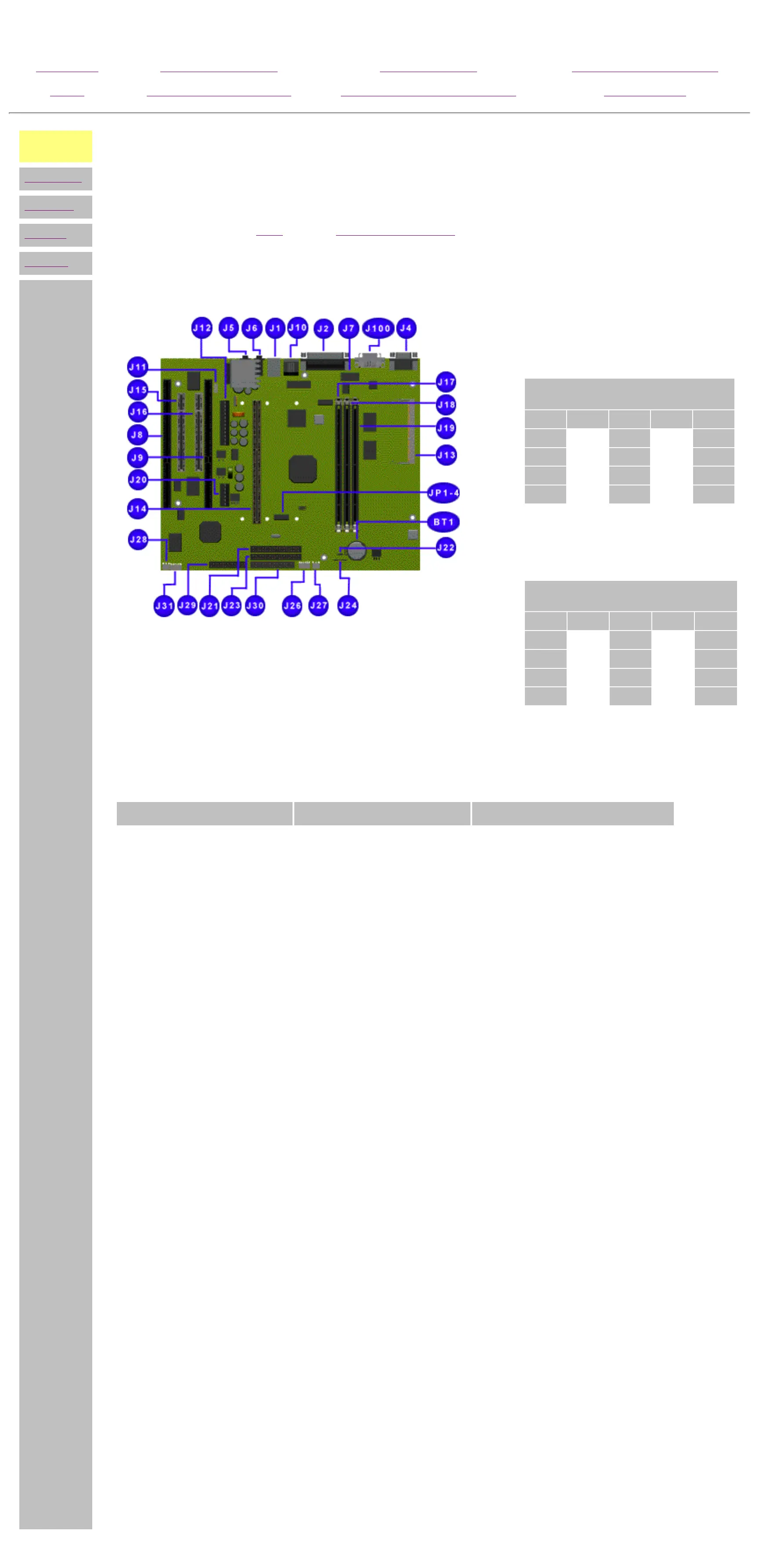
JUMPER & SWITCH INFORMATION
5200 Series System Boards (2nd board of 2)
Click the links for the other 5200 series or 5070, 5184, and 5185 boards.
Click on a jumper designator to find the jumper function and connector description.
Two tables are given below: the first is for a 66
MHz bus speed, the other for 100 MHz bus
speed.
Processor frequency required,
MHz
Jumper
200* 233* 266 300 333
JP1 off on off on off
JP2 on on off off on
JP3 off off on on on
JP4 off off off off off
*Not shipped in these configurations
For a 100 MHz bus speed:
Processor frequency required,
MHz
Jumper
300* 350 400 450 500*
JP1 off on off on off
JP2 on on off off on
JP3 off off on on on
JP4 off off off off off
*Not shipped in these configurations
Connector information
Function Description Reference Designator
Keyboard Miniature 6-pin ½ J1
Mouse Miniature 6-pin ½ J1
Parallel port DSUB 25-pin J2
Video 15-pin VGA J4
Flat panel display 20-pin J100
Ethernet jack RJ45 J10
Microphone in Mini stereo ½ J6
Speaker out Mini stereo ½ J5
Line in Mini stereo ½ J6
Line out Mini stereo ½ J5
DIMM sockets 168-pin DIMM J17, J18, J19
SODIMM socket 144-pin SODIMM J13
PCI slots 32-bit PCI connector J15, J16
ISA slots 16-bit ISA connector J8, J9
Processor slot Slot 1 connector J14
Slot 1 clock multiplier 2-pin header JP1 -- JP4
Clear CMOS 3-pin header J22
Serial port DB9 J7
GamePort/USB 24-pin 2mm connector J29
Sleep button & LEDs 5-pin 2mm connector J26
Battery socket 2-pin socket BT1
CD-ROM audio 4-pin header, key 2 J11
IDE drives 40-pin headers, key 20 J23 (primary), J21 (secondary)
Diskette drive 34-pin header J30
Headphone board 5-pin 2mm connector J31
Internal speakers 2-pin header J27, J28
Second fan 4-pin header, key 2 J24
+3.3V power 6-pin header J20
Power supply 12-pin ATPWR header J12
privacy statement
legal notices
http://h18000.www1.hp.com/athome/support/msgs/5000/bd2jm.html [12/10/2002 9:35:29 AM]
 Loading...