United States
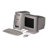
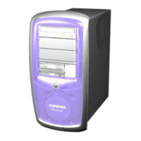
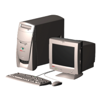
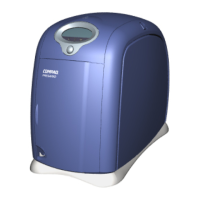
Compaq Presario Internet PC 5000 Series Computers
REMOVAL AND REPLACEMENT PROCEDURES
PRODUCT DESCRIPTION TROUBLESHOOTING ILLUSTRATED PARTS CATALOG
REMOVAL AND REPLACEMENT PROCEDURES
JUMPER AND SWITCH INFORMATION SPECIFICATIONS
ELECTROSTATIC
DISCHARGE
SERVICE
CONSIDERATIONS
PREPARATION FOR
DISASSEMBLY
SERIAL NUMBER
SIDE ACCESS PANEL
GRAPHICS CARD
EXPANSION CARD
(Modem or Network
Card)
1394 CARD
MEMORY MODULE
HARD DRIVE
DISK DRIVE
REMOVING THE TOP
DOOR
REMOVING THE CD
STORAGE DOOR
(Lower Front Panel -
Open the CD Storage
Door)
Service Considerations
Tool Requirements
Phillips screwdriver
1.
Needle-nose pliers2.
Flathead screwdriver3.
Compaq Utilities software4.
Screws
The screws used in these products are not interchangeable. If an incorrect screw is used during
the reassembly process, it could cause damage to the unit. Compaq strongly recommends that
all screws removed during the disassembly process be kept with the corresponding part that was
removed, then returned to their proper locations.
Important
As each subassembly is removed from the computer, it should be
placed away from the work area to prevent damage.
Cables and Connectors
Most cables used throughout the unit are ribbon cables. These must be handled carefullyto avoid
damage. Apply only the tension required to seat or unseat the cable during its insertion or
removal from the connector. Handle cables by the connector whenever possible. In all cases,
avoid bending, twisting, or tearing the cables, and ensure that they are positioned so that they
cannot be caught or snagged by parts being removed.
CAUTION
When servicing these computers, ensure that cables are placed in
their proper location during the reassembly process. Improper
cable placement can cause severe damage to the unit.
 Loading...
