5.4.2 Parallel Interface
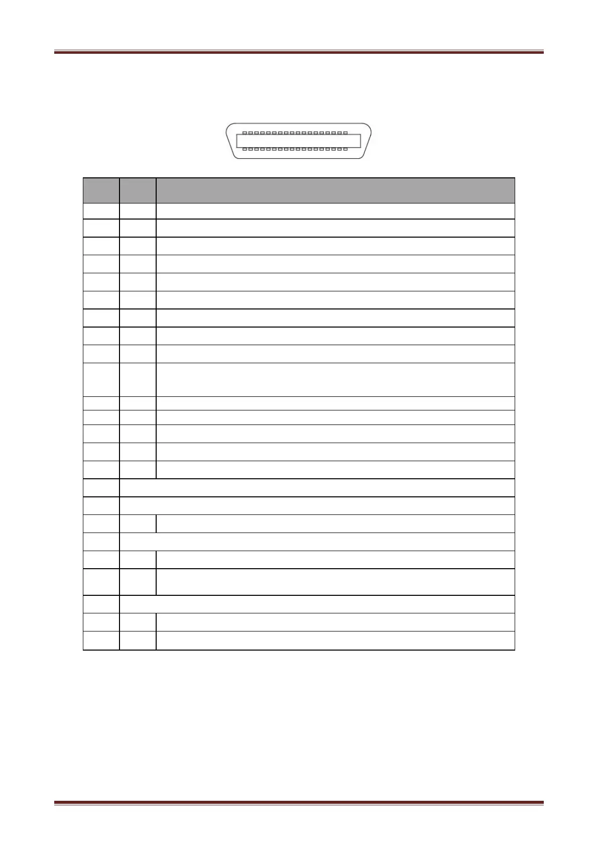
Parallel interface supports protocol with 36 pin CENTRONICS socket.
Figure 5.4.2
Data latch pulse, latch the data to the printer at the rising edge of the negative
pulse
Printer response signal, indicates that the printer has received the last byte of data;
A negative pulse of about 1us.
Busy Signal; The printer is busy; High level indicates that the printer can’t receive
data.
PE Signal; paper end signal; High level indicates that the printer is paper end.
Frame Ground, separated from logic ground
Printer error signal, low level indicates that error occurs in the printer, the error
signal will output along with paper end signal.
Note: H indicates that signal comes from Host computer, P indicates that signal comes from
Printer.