25
ENGLISH
COMUNELLO ®Copyright 2021 - All rights reserved
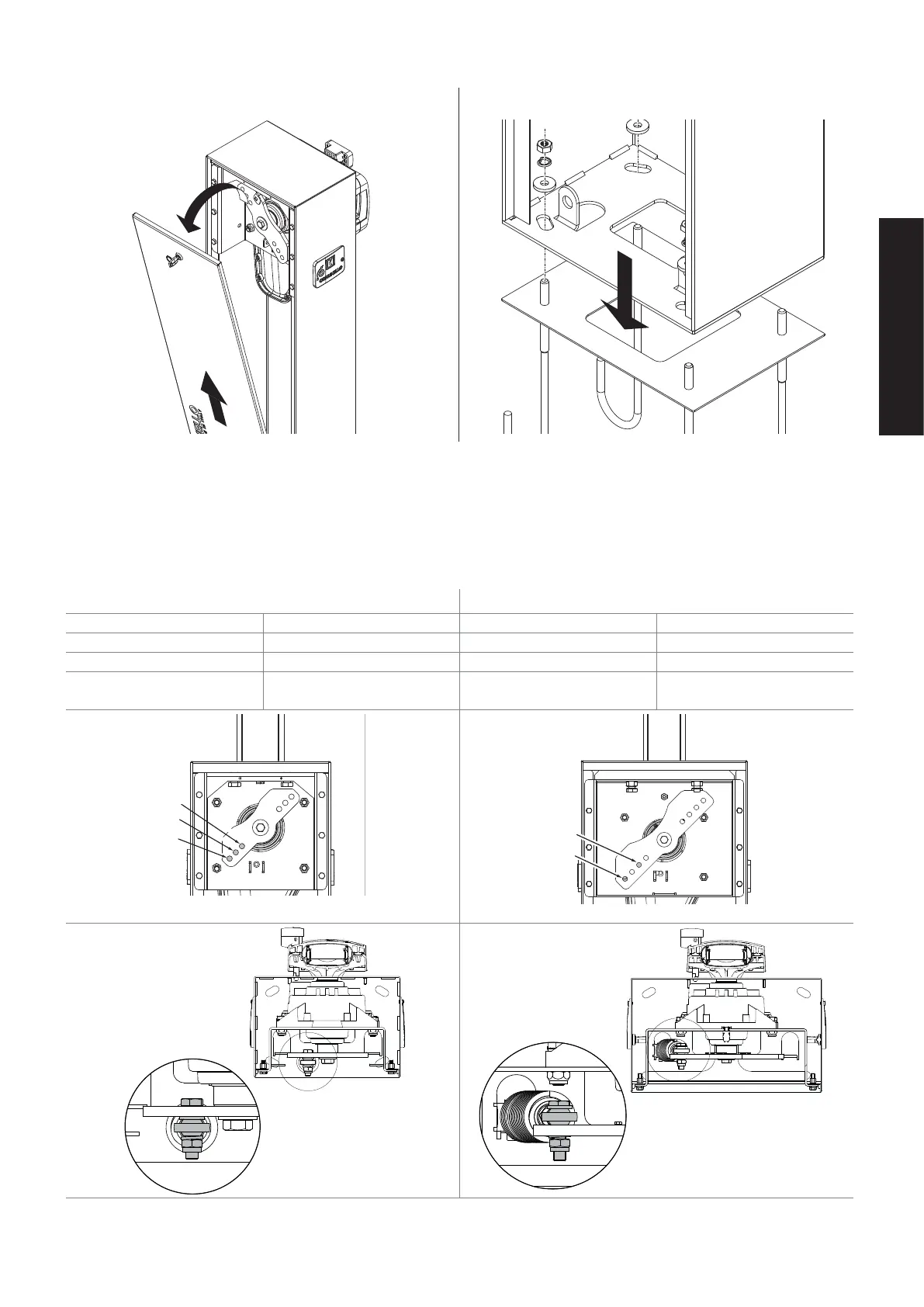
FIG. 4 FIG. 5
Fitting the springs:
The manually operated BORDER 400-600 barrier system features a single- or double-spring mechanism. The spring assembly must
be mounted in the corresponding bore according to the length of the boom as shown in the following table:
• Place the boom holder in an upright position.
• Secure the spring between the frame and the spring tensioning arm (TAB.01).
TAB.01
BORDER 400 BORDER 600
A 3 m D 5 m
B 3m + skirt E 5m + skirt
B 4 m E 6 m
C 4m + skirt E
6m + skirt (double spring
balancing, FIG.6C)
A
C
B
D
E
To install the boom on the opposite side, the conguration is as shown in FIG. 6B.