24
COMUNELLO ®Copyright 2021 - All rights reserved
4.2 LIMITS OF USE
• Use a xed end rest for booms more than 3 m long.
Before installing the barrier, check that its data are within the limits of use in chapter 3: “Product technical specications”.
4.3 INSTALLATION WORKS
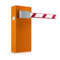
• Assemble the counter plate with the (optional) anchor bolts, allowing them to protrude by approx. 30 mm (FIG. 2-2A).
FIG. 2 FIG. 2A
BORDER 400 BORDER 600
155 mm
240 mm
30 mm
177 mm
30 mm
354 mm
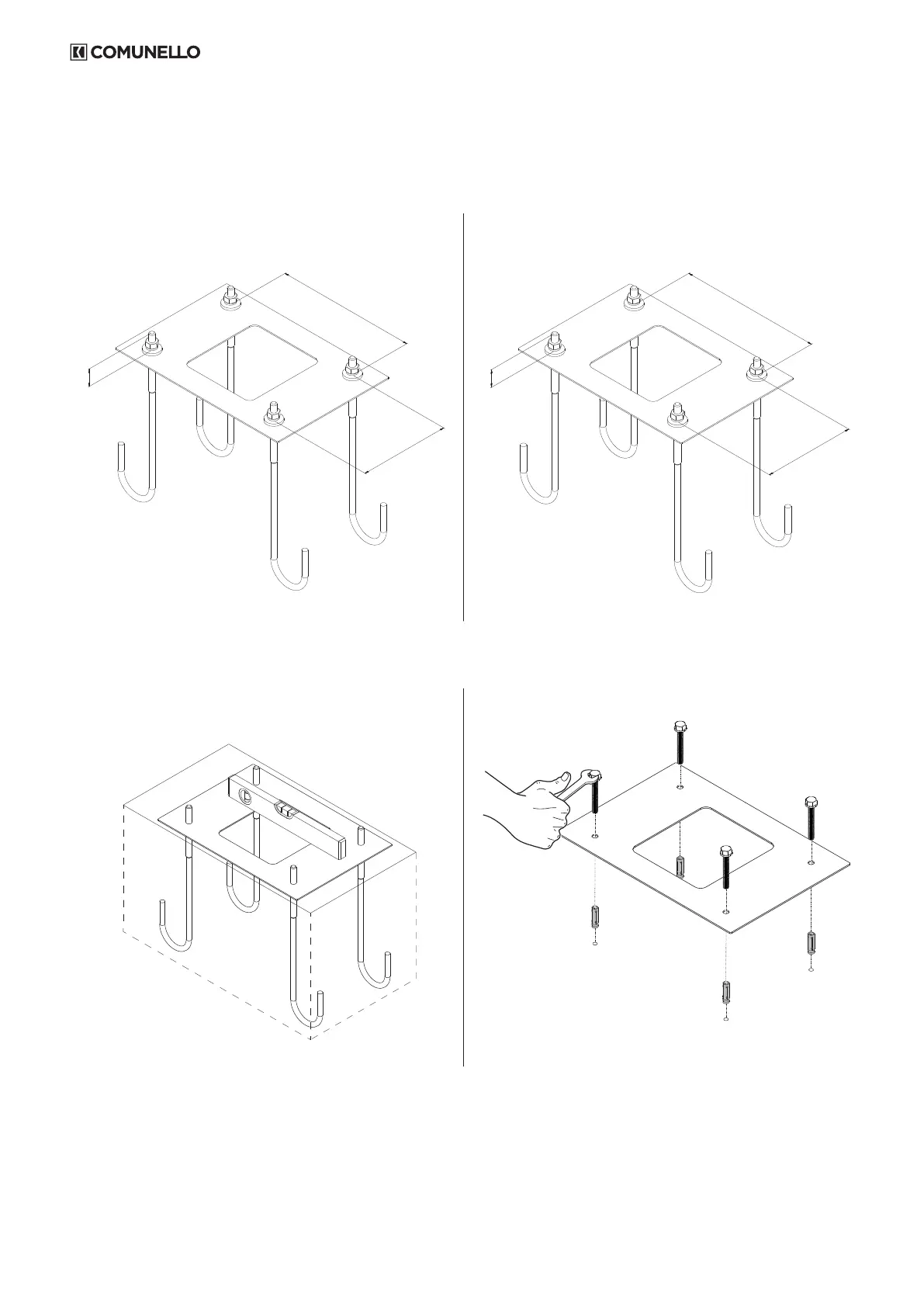
• Embed counter plate and anchor bolts in concrete (FIG.3A).
• In the case of an existing concrete footing drill 4 holes for the screw anchors as shown in FIG. 3B.
FIG. 3A FIG. 3B
4.4 INSTALLATION OF THE MANUALLY OPERATED BORDER BARRIER SYSTEM
4.4.1 INSTALLATION
• Remove the front cover using the supplied key (FIG. 4).
• Position the barrier on the counter plate. Secure the pedestal with the nuts and washers supplied (FIG. 5).