One Conair Drive ● Pittsburgh, PA 15202 ● 412-312-6000 ● FAX 412-312-6227 ● www.conairnet.com
MODELS GB122 GB131 GB140
Performance characteristics
Batch size lbs {g} 2.2 {1000} 2.2 {1000} 2.2 {1000}
Maximum throughput lbs/hr {kg/hr}* 200 {90} 280 {128} 450 {204}
Bin capacity - main ingredient ft
3
{liter} 1.0 {28.32} 1.0 {28.32} 1.0 {28.32}
Bin capacity - minor ingredient ft
3
{liter} 0.5 {14.16} 0.5 {14.16} 0.5 {14.16}
Maximum number of materials 4 4 4
Number of discharge valves 2 3 4
Number of micro pulsing valves 2 1 0
Control software (# of components) 4 or 12 4 or 12 4 or 12
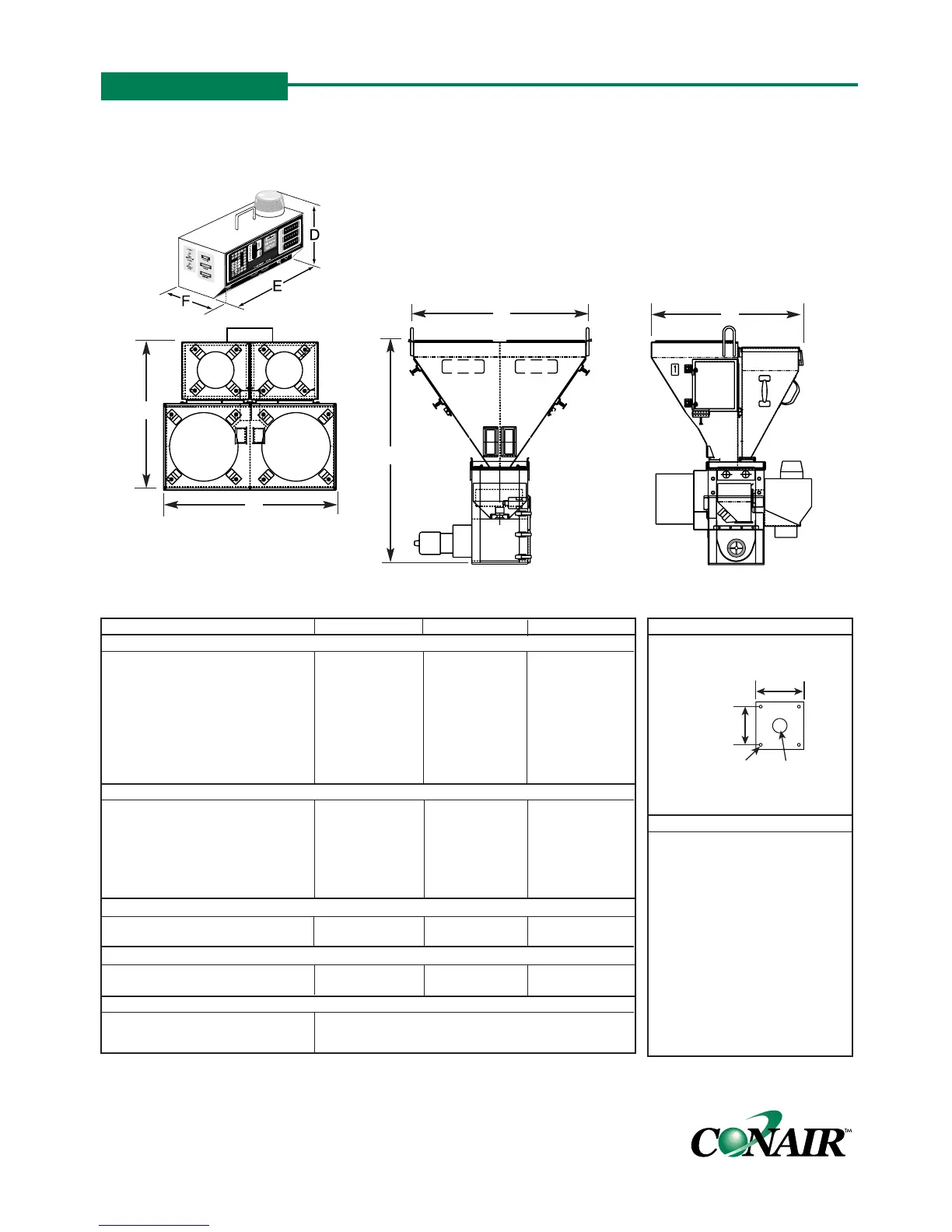
Dimensions inches {mm}
A - Height above mounting plate
†
38.9 {989.6} 38.9 {989.6} 38.9 {989.6}
B - Width 33.2 {843.3} 33.2 {843.3} 33.2 {843.3}
C - Depth 31.4 {797.6} 31.4 {797.6} 31.4 {797.6}
D - Controller height 11.25 {285.75} 11.25 {285.75} 11.25 {285.75}
E - Controller width 12.25 {311.15} 12.25 {311.15} 12.25 {311.15}
F - Controller depth 8.19 {208.03} 8.19 {208.03} 8.19 {208.03}
Weight lbs {kg}
Installed 200 {90.7} 200 {90.7} 200 {90.7}
Shipping 300 {136.1} 300 {136.1} 300 {136.1}
Voltage Total amps
120V/1 phase/50-60 hz 2.0 2.0 2.0
240V/1 phase/50-60 hz 1.0 1.0 1.0
Compressed air requirements
Discharge valves 80 psi @ 0.2 ft
3
/min {5.5 bars @ 0.09 liters/sec}; 1/4 in. NPT fitting
Micro pulsing valves 40 psi @ 0.2 ft
3
/min {2.8 bars @ 0.09 liters/sec}; 1/4 in. NPT fitting
GRAVIMETRIC BATCH BLENDERS
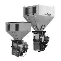
AutoWeigh GB100 Series Models
MOUNTING INTERFACE
SPECIFICATION NOTES:
Each stationary bin compart-
ment can support a 12-inch
loader or vacuum receiver.
Removable bins can support a
maximum of an 8-inch loader.
* Throughput rates are based on
bins with each micro-pulsing
valve dispensing no more than
1% colorant and/or additive
material and using a material
with a bulk density of 35 lb/ft
3
.
†
The optional flow control valve
adds 6.5 in. {165 mm} to total
height.
SPECIFICATIONS
TPBS010/1199
CONTROL
FRONT VIEW
SIDE VIEW
TOP VIEW
C
B
B
A
C
(4) 9/16 in.
3 in. {76.2 mm}
8 in. {203.2 mm}
10 in.


 To Next Page