button" to enter its setting interface shown in Figure 9.
Press the "up button" or "down button" to select the option to be adjusted, then press the "left button" or "right
button" to change the value.
“SpO
2
HI(%)”: upper limit prompt for SpO
2
over-limit
“SpO
2
LO(%)”: lower limit prompt for SpO
2
over-limit
“PR HI(bpm)”: upper limit prompt for PR over-limit
“PR LO(bpm)”: lower limit prompt for PR over-limit
“Prompt Sound”: prompt for over-limit, low-battery, finger out, sensor off and sensor fault, “off”: close, “on”:
open.
“Pulse Sound”: PR sound, “off”: close, “on”: open.
Lower limit can not exceed the upper limit, and the upper limit can not be lower than the lower limit when
adjusting the values. SpO
2
range: 0 % ~ 100 %, PR range: 0 ~ 254 bpm
The values displayed in Figure 9 are the initial values of over-limit prompt.
After setting, press the "menu button" to exit the Prompt Settings Menu interface, and return to “Main Menu”
interface.
5.5.2 Data storage
Under the main menu, press the "up button" or "down button" to select “Record”, then press the "up button" or "down
button" to enter the “Record Menu” interface as shown in Figure 10.
Press the "up button" or "down button" to select the option to be adjusted, then press the "left button" or "right
button" to change the value.
It indicates that the device is storing when the red dot “REC ●” in measurement interface flickers.
“Mode”: record mode selection, including: “Auto” and “Manual” mode. Under “Manual” mode, select to turn on / off
memory by “Record ”.
Auto record: start recording after stable data appear, pull out the finger to finish recording a group of data (99 group of
data at most), the total duration does not exceed 72 hours.
Manual record: after manual storage is started, the storage state needs to be terminated manually to complete a group of
store, store up to 24-hour data.
When the memory is full, it will display “Memory is full!”, then it will enter the standby mode after several seconds.
When exiting the standby mode next time, it will display “Memory is full!” to prompt user that the memory has been
full.
Under manual mode, when “Record” is “ON”, the device will prompt to clear the data stored last time.
It will display “Recording...” when there is no operation under record state for 15s, then it will enter energy saving mode
after several seconds, pressing the "power on/off button", the device would return to the former interface; pressing
any button(power on/off excluded), it will display “Recording...”.
Under data recording state, after the display screen turns off automatically, in order to save power, pulse
sound indication will turn off automatically.
“Seg”: data segment.
After setting, press the "menu button" to exit storage menu, return to main menu.
“Delete All”: delete all records (auto record mode is shown as Figure 10).
Please upload data in time after recording, otherwise the data may be covered when the storage space is full.
The historical data will be deleted once switching the mode. Under record state, the record mode can not be
switched; under manual mode, the record mode can be switched only when turning off recording firstly.
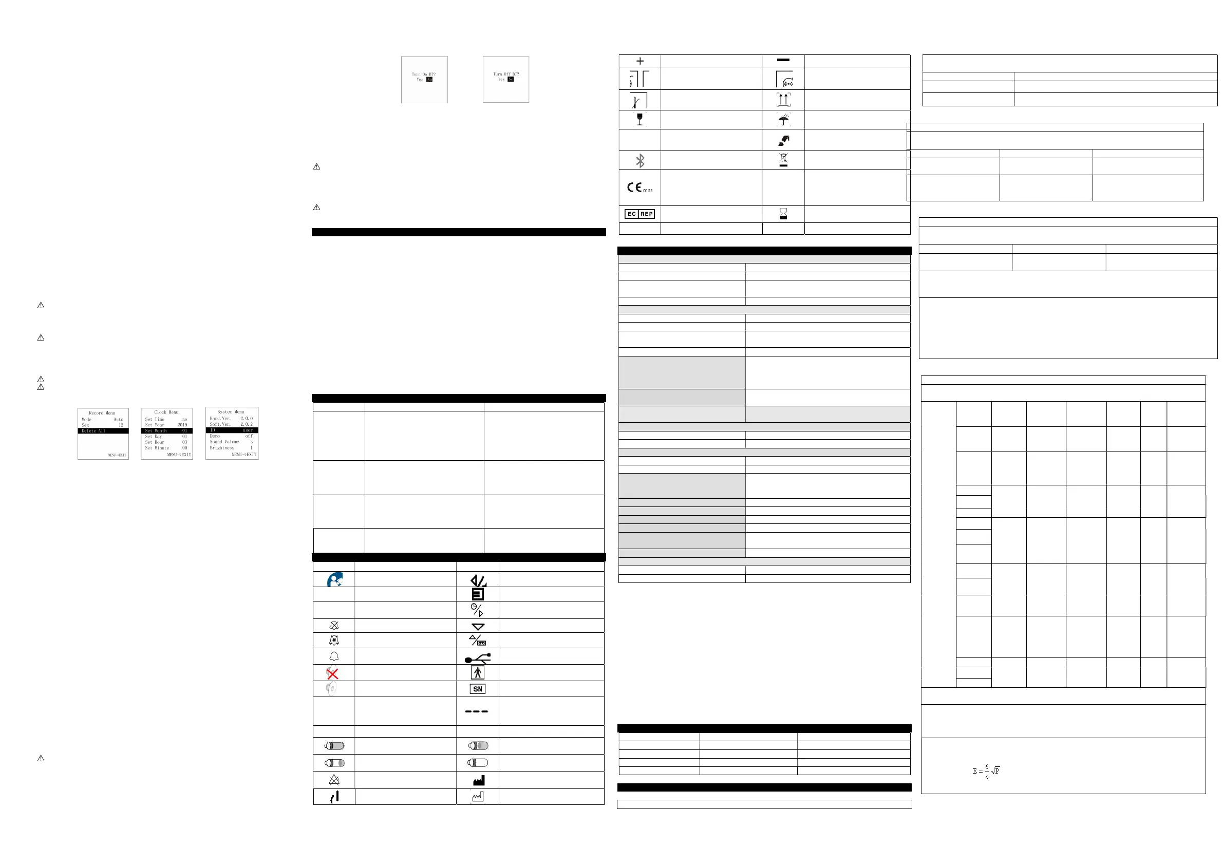
Figure 10 Record menu Figure 11 Clock menu Figure 12 System menu
5.5.3 Clock setting
a. Connect the master device to synchronize device time
Under the PC software interface, after search for the device (refer to relative chapter (5.6) for the connection method), then
can synchronize the device time.
b. Set device time manually
Under main menu, press the "up button" or "down button" to select “Clock”, then press the "left button" or "right
button" to enter its setting interface shown in Figure 11.
Press the "up button" or "down button" to select the option to be adjusted, then press the "left button" or "right
button" to change the value.
“Set Time”: set the time, “yes”: allow, “no”: prohibit
“Set Year”: set the year
“Set Month”: set the month
“Set Day”: set the day
“Set Hour”: set the hour
“Set Minute”: set the minute
Adjustable range for year: 2015 ~ 2045, month: 1 ~ 12, day: 1 ~ 30 (when there are 31 days in a month, it is 1 ~ 31), hour: 1
~ 23, minute: 1 ~ 59.
After setting, press the "menu button" to exit clock menu, return to main menu.
5.5.4 System setting and other options introduction
Under main menu, press the "up button" or "down button" to select “System”, then press the "left button" or "right
button" to enter the interface as shown in Figure 12.
Press the "up button" or "down button" to select the option to be adjusted, then press the "left button" or "right
button" to change the value.
“Hard.Ver.”: hardware version
“Soft.Ver.”: software version
“ID”: user name
“Demo”: set the Demo mode, “on”: turn on the Demo mode, “off”: turn off the Demo mode.
“Sound Volume”: set the sound volume, adjustable range: 1 ~ 3
“Brightness”: set the screen brightness, adjustable range: 1 ~ 4
After setting, press the "menu button" to exit system setting menu, return to main menu.
5.5.5 Bluetooth setting (Bluetooth equipment)
Under main menu, press the "up button" or "down button" to select “Bluetooth”, then press the "left button" or "right
button" to enter its selection interface as shown in Figure 13 and Figure 14 When the Bluetooth is “ON’,if no data is
transmitted for some time, then the Bluetooth will be turned off automatically.
Under transmitting data by Bluetooth, the Bluetooth can not be turned off.
Figure 13 Bluetooth “ON” interface Figure 14 Bluetooth “OFF” interface
5.5.6 Exit main menu
Under main menu, press the "menu button" to exit the main menu and return to the measurement interface.
5.6 Data upload
A. Wired transmission
Connect the device to the computer by the USB cable, upload the data after connecting the PC software properly, refer to “Software
operating instruction” for details.
The PC software can be downloaded from our official website.
B. Bluetooth transmission (Bluetooth equipment)
Turn on the device Bluetooth and the PC software to upload data, refer to “Software operating instruction” for details.
5.7 Power off
Long press the "power on/off" button, until the device turns off.
when the device is in storing , it can’t be turned off.
6 Maintain, Transport and Storage
6.1 Cleaning and disinfection
The device must be turned off before cleaning, and it should not be immersed into liquid.
Please take out the internal battery before cleaning, do not immerse it into liquid.
Use 75% alcohol to wipe the device enclosure, nature dry or clean it with clean and soft cloth. Do not spray any liquid on the
device directly, and avoid liquid penetrating into the device.
6.2 Maintenance
A. Check the main unit and all accessories periodically to make sure that there is no visible damage that may affect patient’s
safety and monitoring performance. It is recommended that the device should be inspected weekly at least. When there is
obvious damage, stop using it.
B. Please clean and disinfect the device before/after using it according to the User Manual (6.1).
C. Please replace the batteries in time when low-battery appears.
D. Please take out the batteries if the device is not used for a long time.
E. The device need not to be calibrated during maintenance.
6.3 Transport and Storage
A. The packed device can be transported by ordinary conveyance or according to transport contract. During transportation, avoid
strong shock, vibration and splashing with rain or snow, and it can not be transported mixed with toxic, harmful, corrosive
material.
B. The packed device should be stored in room with no corrosive gases and good ventilation. Temperature: -40°C~+60°C;
Relative humidity: ≤95%.
7 Troubleshooting
Trouble Possible Reason Solution
The values can
not be displayed
normally or
stably.
1) The finger is not properly inserted.
2) The finger is shaking or the patient is
moving.
3) The device is not used in environment
required by the manual.
4) The device works abnormally.
1) Please insert the finger properly and
measure again.
2) Let the patient keep calm.
3) Please use the device in normal
environment.
4) Please contact the after-sales.
The device can
not be turned on
1) The battery is drained away or almost
drained away.
2) The battery is installed incorrectly.
3) The device’s malfunction.
1) Please change batteries.
2) Please Install the battery again.
3) Please contact the local service center.
The display
disappears
suddenly.
1) The device enters into the energy saving
mode.
2) Low battery.
3) The device works abnormally.
1) Normal.
2) Please change batteries.
3) Please contact the after-sales.
The data can not
be stored.
1) The device is not operated according to the
manual.
2) The device works abnormally.
1) Please operate the device according to the
manual.
2) Please contact the after-sales.
8 symbols
Symbols Meaning Symbols Meaning
Caution, consult accompanying
documents
left button/prompt pause button
%SpO
2
pulse oxygen saturation (%)
Menu button
PRbpm
Pulse rate (bpm)
Right button/clock button
Close the sound prompt
down button
Pause the sound prompt
Up button/replay button
Open the sound prompt
USB
Close the PR sound
Type BF applied part
Open the PR sound
Serial number
Finger Out
The finger is not inserted.
1. The finger clip falls off ( no finger
inserted)
2. Probe error
3.Signal inadequacy indicator
Sensor Off
The probe is disconnected.
Sensor Fault
Probe failure
The battery power is full
Two grid of the battery
One grid of the battery
The lack of battery power.(Please change
batteries in time for exact measuring)
Alarm inhibit
Manufacturer
Power on/off button
Manufacture Date
Battery anode
Battery cathode
Temperature limitation
Atmospheric pressure limitation
Humidity limitation
This way up
Fragile, handle with care
Keep away from rain
IP22
It means this pulse oximeter is
protected against harmful effects of
dripping water when tilted at 15°
Recyclable
Bluetooth: ON
(Bluetooth equipment)
Recycling garbage
WEEE (2012/19/EU)
This item is compliant with Directive
93/42/EEC of 14 june 1993 concerning
medical devices; Including, at 21 march
2010, the amendments by Council
Directive 2007/47/EC.
REC●
Record state
European Representative
Use-by date
LOT Batch No. P/N Material code
Note:Your device may not contain all the following symbols.
9 Specification
SpO
2
[see note 1]
Display range 0% ~ 100%
Measured range 0% ~ 100%
Accuracy [see note 2]
70%~100%: ±2%;
0%~69%: unspecified.
Resolution 1%
PR
Display range 30 bpm ~ 250 bpm
Measured range 30 bpm ~ 250 bpm
Accuracy [see note 3]
±2 bpm during the pulse rate range of 30 bpm ~ 99 bpm and ±2%
during the pulse rate range of 100 bpm ~ 250 bpm.
Resolution 1 bpm
Accuracy under low perfusion [see note 4]
Low perfusion 0.4%:
SpO
2
: ±4%;
PR: ±2 bpm during the pulse rate range of 30 bpm ~ 99 bpm and
±2% during the pulse rate range of 100 bpm ~ 250 bpm.
Light interference
Under normal and ambient light conditions, the SpO
2
deviation ≤
1%
Pulse intensity
Continuous bar graph display, the higher display indicates the
stronger pulse.
Upper and lower limit of measured values
SpO
2
0% ~ 100%
PR 0 bpm ~ 254 bpm
Optical sensor [see note 5]
Red light Wavelength: about 660 nm, optical output power: < 6.65 mW
Infrared light Wavelength: about 905 nm, optical output power: < 6.75 mW
Memory
Up to 99 group of data under auto mode, total duration does not
exceed 72 hours.
Up to 24-hour data under manual mode.
Safety class Internally powered equipment, type BF applied part
International Protection IP22
Working voltage DC 2.6 V ~ 3.6V
Working current ≤ 100 mA
Operation time
The device can continuously work for 24 hours when it was
powered by two new batteries within the warranty period.
Power supply Dry battery (2AA)
Dimension and Weight
Dimensions 110(L) × 60(W) × 24(H) mm
Weight About 120g (with Dry battery(2AA))
Note 1: the claims of SpO
2
accuracy shall be supported by clinical study measurements taken over the full range. By
artificial inducing, get the stable oxygen level to the range of 70 % to 100 % SpO
2
, compare the SpO
2
values collected by
the secondary standard pulse oximeter equipment and the tested equipment at the same time, to form paired data, which
are used for the accuracy analysis.(It is applicable for the probes equipped.)
There are 12 healthy volunteers (male: 6. female: 6; age: 18~50; skin color: black: 2, light: 8, white: 2) data in the clinical
report.
Note 2: because pulse oximeter equipment measurements are statistically distributed, only about two-thirds of pulse
oximeter equipment measurements can be expected to fall within ±Arms of the value measured by a CO-OXIMETER.
Note 3: Patient simulator has been used to verify the pulse rate accuracy, it is stated as the root-mean-square difference
between the PR measurement value and the value set by simulator.
Note 4: percentage modulation of infrared signal as the indication of pulsating signal strength, patient simulator has
been used to verify its accuracy under conditions of low perfusion. SpO
2
and PR values are different due to low signal
conditions, compare them with the known SpO
2
and PR values of input signal.
Note 5: optical sensors as the light-emitting components, will affect other medical devices applied the wavelength range.
The information may be useful for the clinicians who carry out the optical treatment.For example, photodynamic
therapy operated by clinician.
Appendix
State Sound prompt condition delay Sound prompt signal generation delay
Low voltage sound prompt 1s 20ms
SpO
2
sound prompt 330ms 20ms
Pulse rate sound prompt 330ms 20ms
Probe error sound prompt 16ms 20ms
EMC
Table 1:
Guidance and manufacturer’s declaration –electromagnetic emission
The Pulse Oximeter is intended for use in the electromagnetic environment specified below. The purchaser or the user of the
device should assure that it is used in such environment.
Emission test Compliance
RF emissions CISPR 11 Group 1
RF emissions CISPR 11 Class B
Table 2:
Guidance and manufacturer’s declaration-electromagnetic immunity
The Pulse Oximeter is intended for use in the electromagnetic environment specified below. The purchaser or the user of the Pulse
Oximeter should assure that it is used in such environment.
Immunity test IEC60601 test level Compliance level
Electrostatic discharge (ESD)
IEC 61000-4-2
±8kV contact
± 15 kV air
±8kV contact
±15kV air
Power frequency (50 / 60Hz)
magnetic field
IEC 61000-4-8
30 A/m 30A/m
Table 3:
Guidance and manufacturer’s declaration – electromagnetic immunity
The Pulse Oximeter is intended for use in the electromagnetic environment specified below. The customer the user of the Pulse
Oximeter should assure that it is used in such environment.
Immunity test IEC 60601 test level Compliance level
Radiated RF
IEC61000-4-3
10 V/m 80 MHz- 2.7 GHz 10 V/m80 MHz- 2.7 GHz
NOTE 1 At 80 MHz and 800 MHz, the higher frequency range applies.
NOTE 2 These guidelines may not apply in all situations. Electromagnetic propagation is affected by absorption and reflection from
structures, objects and people.
a Field strengths from fixed transmitters, such as base stations for radio (cellular/cordless) telephones and land mobile radios,
amateur radio, AM and FM radio broadcast and TV broadcast cannot be predicted theoretically with accuracy. To assess the
electromagnetic environment due to fixed RF transmitters, an electromagnetic site survey should be considered. If the measured field
strength in the location in which the Pulse Oximeter is used exceeds the applicable RF compliance level above, the Pulse Oximeter
should be observed to verify normal operation. If abnormal performance is observed, additional measures may be necessary, such as
reorienting or relocating the Pulse Oximeter.
b Over the frequency range 150 KHz to 80 MHz, field strengths should be less than 3V/m.
Table 4:
Guidance and manufacturer’s declaration - electromagnetic Immunity
The [Code SI] is intended for use in the electromagnetic environment specified below. The customer or the user of the Pulse
Oximeter should assure that it is used in such an environment
Radiated RF
IEC61000-4-
3
(Test
specification
s for
ENCLOSU
RE PORT
IMMUNITY
to
RF wireless
communicati
ons
equipment)
Test
Frequency
(MHz)
Band a)
(MHz)
Service a) Modulation b)
Modulation
b)
(W)
Distance
(m)
IMMUNITY
TEST LEVEL
(V/m)
385 380 –390 TETRA 400
Pulse
modulation b)
18 Hz
1,8 0,3 27
450 430-470
GMRS 460,
FRS 460
FM c)
± 5 kHz
deviation
1 kHz sine
2 0,3 28
710
704 – 787
LTE Band
13,17
Pulse
modulation b)
217 Hz
0,2 0,3 9
745
780
810
800 – 960
GSM 800/900,
TETRA 800,
iDEN 820,
CDMA 850,
LTE Band 5
Pulse
modulation b)
18 Hz
2 0,3 28
870
930
1720
1700 –
1990
GSM 1800;
CDMA 1900;
GSM 1900;
DECT;
LTE Band 1,
3,4,25; UMTS
Pulse
modulation b)
217 Hz
2 0,3 28
1845
1970
2450 2400 –2570
Bluetooth,
WLAN,
802.11 b/g/n,
RFID 2450,
LTE Band 7
Pulse
modulation b)
217 Hz
2 0,3 28
5240
5100 –5800
WLAN 802.11
a/n
Pulse
modulation b)
217 Hz
0,2 0,3 9
5500
5785
NOTE If necessary to achieve the IMMUNITY TEST LEVEL, the distance between the transmitting antenna and the ME
EQUIPMENT or ME SYSTEM may be reduced to 1 m. The 1 m test distance is permitted by IEC 61000-4-3.
a) For some services, only the uplink frequencies are included.
b) The carrier shall be modulated using a 50 % duty cycle square wave signal.
c) As an alternative to FM modulation, 50 % pulse modulation at 18 Hz may be used because while it does not represent actual
modulation, it would be worst case.
The MANUFACTURER should consider reducing the minimum separation distance, based on
RISK MANAGEMENT, and using higher IMMUNITY TEST LEVELS that are appropriate for the reduced minimum
separation distance. Minimum separation distances for higher IMMUNITY TEST LEVELS shall be calculated using the
following equation:
Where P is the maximum power in W, d is the minimum separation distance in m, and E is the IMMUNITY TEST LEVEL in
V/m.
 Loading...