CHAPTER 2 –Ha
r
dwa
r
e
I
n
s
tallatio
n
s
10 SPI-6941-LV
2
.
2
C
P
U
In
s
t
a
ll
a
t
ion
:
The SPI-6941-LV Industrial CPU Card supports a single
I
n
t
el
®
C
elero
n
®
(
F
C
-
PG
A
)
or Pe
n
t
i
u
m
®
III
p
roce
ss
or
(
F
C
-
PG
A
or F
C
-
PG
A
2
)
. The CPU core voltage is automatically
adjusted by the voltage regulator on the CPU card, which is connected to the VID pin of the
processor. The processor’s VID pins automatically program the voltage regulator on the CPU
card to the required processor voltage. The host bus speed is automatically selected. The
processor connects to the CPU card through the 370-pins ZIF PPGA socket.
Please change the setting of JP12 in case that you use the CPU other than Tualatine
CPU (PC686-1260). See page 37.
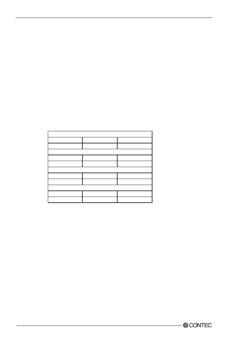
The CPU card supports the processors listed in table below:
Celeron processor (FC-PGA)
Processor Speed Host Bus frequency Cache size
566 MHz to 850MHz 66MHz/100MHz 128KB
Celeron processor (FC-PGA2)
Processor Speed Host Bus frequency Cache size
1.0GHz to 1.2GHz 100MHz 256KB
Pentium III processor (FC-PGA)
Processor Speed Host Bus frequency Cache size
500 MHz to 866MHz 100MHz/133MHz 256KB
Pentium III processor (FC-PGA2)
Processor Speed Host Bus frequency Cache size
1.13GHz to 1.26GHz 133MHz 512KB
The ZIF PPGA socket comes with a lever to secure the processor. Make sure the notch
on the corner of the CPU corresponds with the notch on the inside of the socket.
After you have installed the processor into the socket 370, check if the configuration
setup for the CPU type and speed are correct. The CPU should always have a Heat Sink and a
cooling fan attached to prevent overheating.
N
ote
:
En
s
u
r
e that the CP
U
heat
s
ink and the CP
U
top
s
u
r
face a
r
e in total contact to avoid CP
U
ove
r
heating p
r
oble
m
that would cau
s
e you
r
s
y
s
te
m
to hang o
r
be un
s
table.