CHAPTER 2 –Ha
r
dwa
r
e
I
n
s
tallatio
n
s
SPI-6941-LV 23
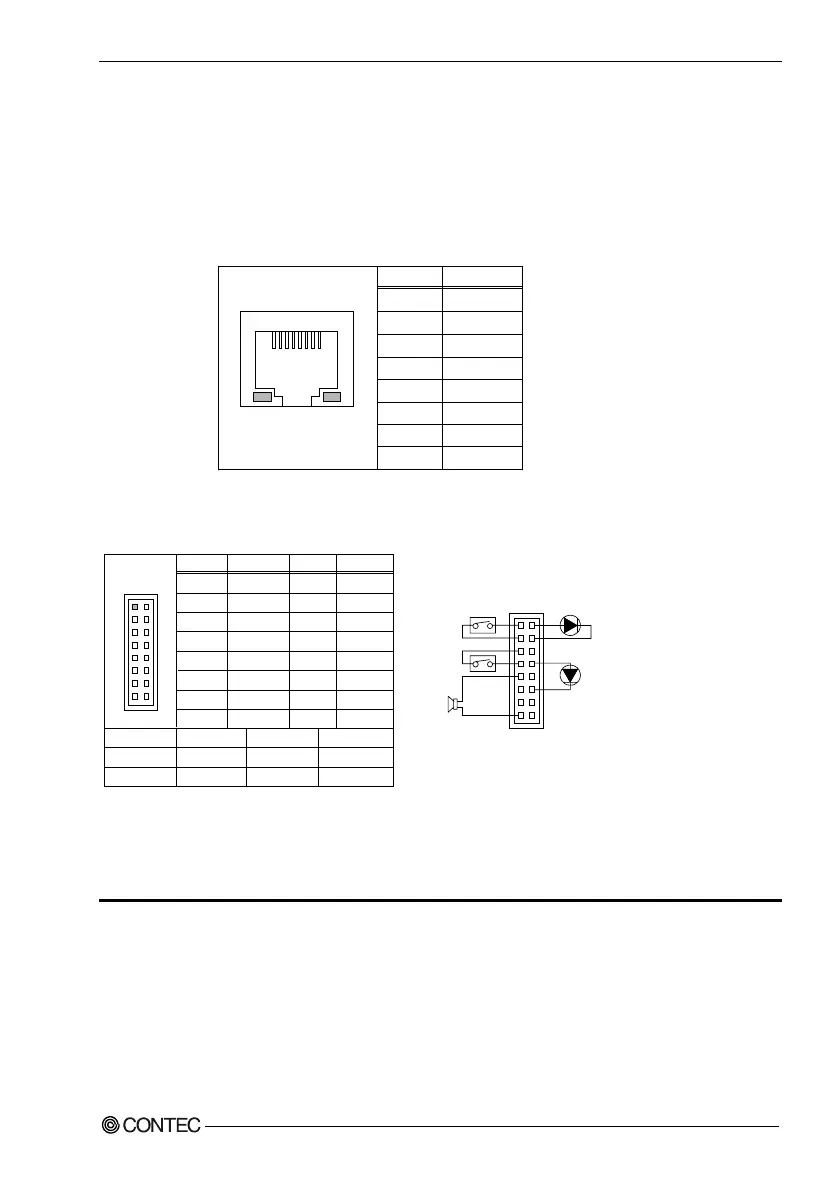
2
.
10
L
AN
c
onn
ec
t
o
r
(
R
J
-
45
):
CN
14
This connector are for the 10/100Mbps Ethernet capability of the CPU card. The follow
table shows the pin assignments of this connector.
The category-5 cable is required for transmission at 100Mbps.
Func
t
ion
T
X
+
T
X
-
R
X
+
N.
C
.
N.
C
.
R
X
-
N.
C
.
N.
C
.
Pin No.
1
2
3
4
5
6
7
8
81
C
N
14
Link &
AC
T
L
E
D
100
M De
t
ec
t
L
E
D
2
.
11
F
r
on
t
P
a
n
e
l
C
onn
ec
t
o
r
:
CN
15
Pin No.
1
3
5
7
9
11
13
15
Func
t
ion
Power
B
T
GND
RE
S
E
T
GND
VCC
GND
GND
B
UZZ
ER
Pin No.
2
4
6
8
10
12
14
16
Func
t
ion
VCC
I
D
E
AC
T
N.
C
.
VCC
VCC
GND
N.
C
.
N.
C
.
S
p
e
a
ker
R
ese
t
B
u
tt
on
Power L
E
D
9
,
11
,
13
,
15
5
,
7
8
,
10
,
12
Power
B
u
tt
on
H
DD L
E
D
1
,
3
2
,
4
C
N
15
1 2
15 16
1
15
H
DD
A
c
t
i
v
e
I
n
d
ic
a
t
or L
E
D
Power L
E
D
Power Swi
t
ch
f
or
A
T
X
E
x
t
ern
a
l S
p
e
a
ker
(
E
x
.
8
Ω
0
.
25
W
)
R
ese
t
Swi
t
ch
This header can be connected to a front panel power switch. The front panel
connector includes headers for these I/O connections:
Powe
r
s
witc
h
Power LED
This header can be connected to an LED that will light when the computer is powered
on.