CHAPTER 2 –Ha
r
dwa
r
e
I
n
s
tallatio
n
s
24 SPI-6941-LV
Ha
r
d d
r
ive activity LE
D
This header can be connected to an LED to provide a visual indicator that data is being
read from or written to an IDE hard drive. For the LED to function properly, the IDE drive must
be connected to the onboard IDE controller.
S
peake
r
A speaker can be installed on the SPI-6941-LV as a manufacturing option. The speaker
is enabled by a jumper on pins 9, 11, 13, 15 of the front panel connector. The speaker (onboard
or offboard) provides error beep code information during the POST in the event that the
computer cannot use the video interface. The speaker is not connected to the audio subsystem
and does not receive output from the audio subsystem.
2
.
12
E
x
t
e
r
n
a
l
B
a
tt
e
r
y
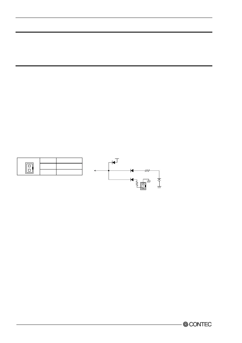
C
onn
ec
t
o
r
:
CN
16
It is a 2 Pin connector used for external battery. An external battery powers the real-
time clock and CMOS memory.
Pin No.
1
2
Func
t
ion
GND
E
x
t
_
ba
t
(
3
V
)
C
N
16
1
2
C
N
16
1
2
3
V
S
B
1
k
Ω
On
b
o
a
r
d
Li
t
iu
m
ba
tt
er
y
+
1
k
Ω
C
MOS Me
m
or
y
R
e
a
l
-
t
i
m
e clock
H
ousin
g
:
X
H
P
-
2
(
J
ST
)
C
on
t
a
c
t
: S
X
H
-
001
T
-
P
0
.
6
(
J
ST
)