4.2 Audio/Visual Display
000
N
Hz
lbs
000
N
Hz
lbs
000
N
Hz
lbs
Visual Measurement Results
Tension displayed in newtons.
Frequency mode, results displayed
as hertz (cycles/sec).
Tension displayed in pounds-force.
A dark oval will appear to indicate the units
associated with the number displayed.
Audible Signals
Signal When Means
One beep Upon release of SPAN key Input accepted
Upon release of MASS key Input accepted
While sensor is aimed at vibrating belt Measurement taken
Two beeps Upon pushing MEM key after releasing SPAN key Span data has been stored
Upon pushing MEM key after releasing MASS key Mass data has been stored
Four beeps Combined with “000” newton display Newton result is out of range
Combined with “000” pound display Pound result is out of range
After pushing ON key and combined with “zero” countdown Low battery condition
The TensionRite® Belt Frequency Meter is an interactive tool. It
provides both visual and audible communication with the operator.
Each signal or combination of signals has meaning. While all these
signals are discussed in other sections of this manual, here will be
presented a compilation of all the available signals.
Generally visual signals alone give measurement results while
audible signals, either alone or in combination with a visual signal,
indicate some operational step.
Gap
3/8 in.
to 2 in.
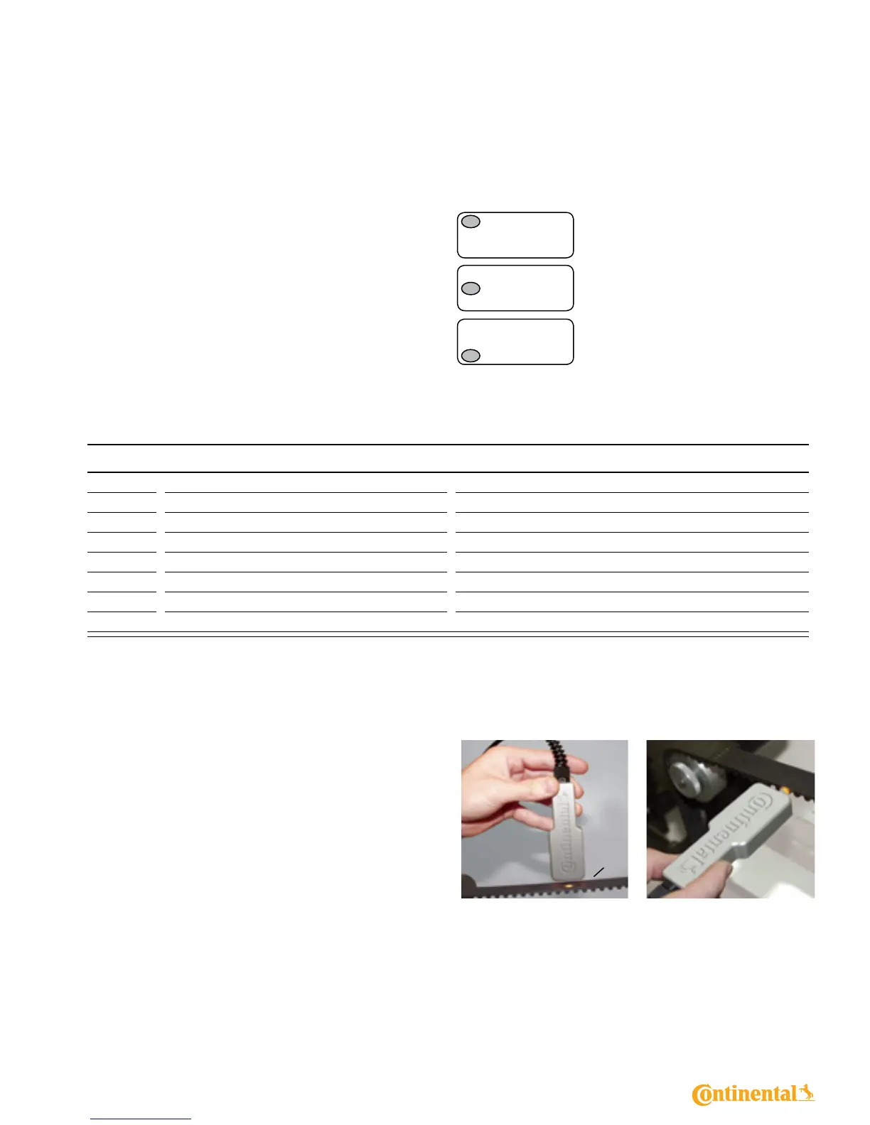
4.3 Optical Sensor
The sensor uses an invisible infrared beam to detect vibrations of
the belt. A narrow angle orange LED-generated beam is provided
to guide the aiming of the sensor.
The very best signal from the belt is seen when the sensor is held
perpendicular to the belt at the center of the span and at a 3/8 in.
(9.5mm) distance. It is also a good practice to orient the long edge
of the sensor head parallel to the centerline of the belt. This helps
reduce the eect of any divergence between the aiming beam and
the infrared sensing beam.
When physical restrictions are present, it is possible to get usable
readings with the sensor at up to 2 in. distance from the belt and/
or tipped up to 45 degrees from perpendicular.
It is possible to take measurements from the edge of the belt.
The toothed side of a belt is equally acceptable as a target for
the sensor.
The sensor LEDs should be kept clean by wiping with a soft
cotton cloth. Solvents are never to be used.
Power Transmission Products 4.0 Functions
7