5901 High Speed Dialup Modem Hardware Manual
October 19, 2007
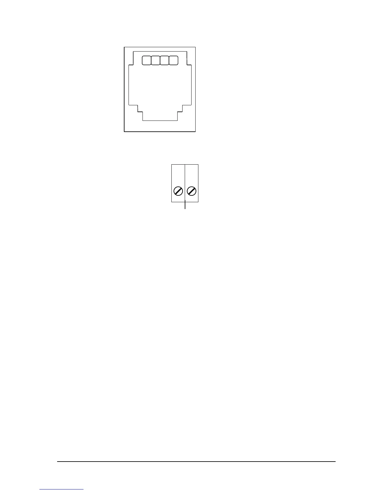
RJ-11 Conections
1. n/c
2. Telephone line Tip
3. Telephone line Ring
4. n/c
Figure 4: 5901 Modem RJ-11 Connection, P6
Figure 5: 5901 Terminal Block Connection, P3
4.4 Power Connections
The 5901 modem may be powered in any one of the following ways:
5VDC applied to the 5901 from the I/O Bus.
9VDC applied to the 5901SA from P5.
5VDC applied to the 5901 from pin 9 on the RS-232 connector, P4.
4.4.1 I/O Bus Connection
The 5901 modem is normally powered through the connection to the system I/O Bus. The 5901
modem is connected to the system I/O Bus using a cable connected to P1 or P2. Refer to the System
Configuration Guide for complete information on the system I/O Bus cabling.
4.4.2 5901 SA Power Connection
The 5901SA version of the modem is powered using a transformer connected to P5. The transformer
plugs into a 120VAC supply and provides 9VDC to the 5901SA. The transformer is shipped with all
5901SA modems. To power the 5901SA modem using the transformer:
Ensure the transformer is not connected to the 120VAC supply.
Locate connector P5 on the 5901 modem. Refer to Figure1: 5901 Module Layout for the
location of P5.
Insert the small female plug on the transformer assembly into connector P5.
Plug the transformer into a 120VAC supply.