2 Unidrive M300 Quick Start Guide
Issue Number: 1
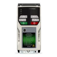
Figure 2-1 Rating label and product identification
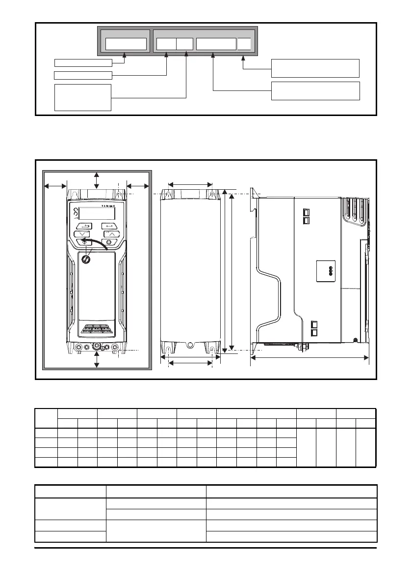
3 Mechanical installation
The drives can be panel mounted with 0 mm space between the drives. For further information on
mechanical installation refer to the Unidrive M300 User Guide.
To remove the terminal cover, use a flat bladed screwdriver to rotate the terminal cover locating clip
by approximately 30° in a counter clockwise direction, and then slide the cover down.
Table 3-1 Recommended torque settings
Drive
Size
HWDM1M2∅ AB
mm in mm in mm in mm in mm in mm in mm in mm in
1 160 6.30 75 2.95 130 5.12 143 5.70 53 2.08 5 0.2
0.00 0.00 100 3.93
2 205 8.07 78 3.07 150 5.91 194 7.63 55 2.17 5 0.2
3 226 8.90 90 3.54 160 6.30 215 8.46 70.7 2.80 5 0.2
4 277 10.91 115 4.53 175 6.89 265 10.43 86 3.40 6 0.23
Model size Terminal block description Torque settings
All
Control terminals 0.2 N m (0.15 Ib ft)
Relay terminals 0.5 N m (0.37 Ib ft)
1
Power terminals
0.5 N m (0.37 Ib ft)
2, 3, 4 1.4 N m (1.03 Ib ft)
Derivative
Electrical Specifications
M300 - 03 4 00073
Product line:
Frame size:
Voltage rating
:
Current Rating :
Heavy Duty current rating x10
Drive Format :
A – AC in AC out
A
1 - 100 V (100 - 120 10 %)
- 400 V (380 - 480 10 %)
5 - 575 V (500 - 575 10 %)
6 - 690 V (500 - 690 10 %)
2 - 200 V (200 - 240 10 %)
4
±
±
±
±
±
A
W
M2
M2
B
D
B
A
H
M1
Cover
release