Unidrive M300 Quick Start Guide 3
Issue Number: 1
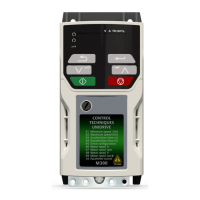
4 Electrical installation
Figure 4-1 below shows an overlay of the electrical connections / terminals available on the drive.
For further information regarding terminal specification, cable sizes etc., refer to the Unidrive M300
User Guide.
Figure 4-1 M300 Overlay of electrical connections
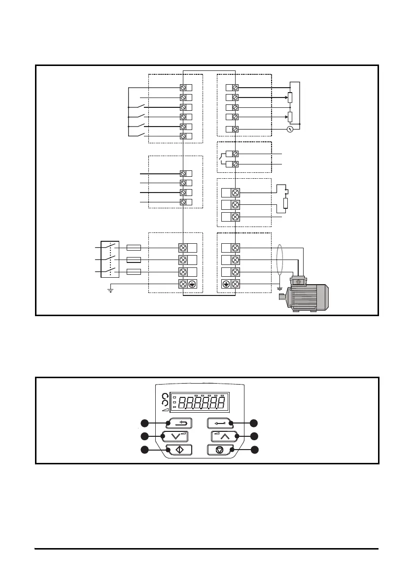
5 Keypad and display
The keypad and display provide information to the user regarding the operating status of the drive and trip
codes, and provide the means for changing parameters, stopping and starting the drive, and the ability to
perform a drive reset.
Figure 5-1 Unidrive M300 keypad detail
(1) The Enter button is used to enter parameter view or edit mode, or to accept a parameter edit.
(2, 5) The Navigation keys can be used to select individual parameters or to edit parameter values. In
keypad mode, the ‘Up’ and ‘Down’ keys are also used to increase or decrease the motor speed.
(3) The Stop / Reset key is used to stop and reset the drive in keypad mode. It can also be used to reset
the drive in terminal mode.
(4) The Start key is used to start the drive in keypad mode.
(6) The Escape key is used to exit from the parameter edit / view mode or disregard a parameter edit.
9
10
11
12
33
Zero frequency
Run forward
User enable 2
/ STO input 2
0VSTO2
34
STO2
13
Run reverse
14
Digital I/O
L1
L2
L3
1 ph/3 ph
AC power
supply
Braking resistor
(optional)
U
BR
+
_
V
W
Thermal relay
41
42
Drive ok
Relay
AC supply
DC bus/Brake
Motor
31
STO1
32
0VSTO1
User enable 1
/ STO input 1
Safe Torque
Off
Analog input 1/
Analog input 2 select
Digital Input 2
24 V user
Digital I/O1
Digital input 3
Digital input 4
Digital input 5
1
2
0V
Analog I/O
Analog input 1+
7
Analog output 1
4
10 V user
5
Analog input 2
Frequency
reference 1
Frequency
reference 2
Frequency output