13
2.5 Solder Links
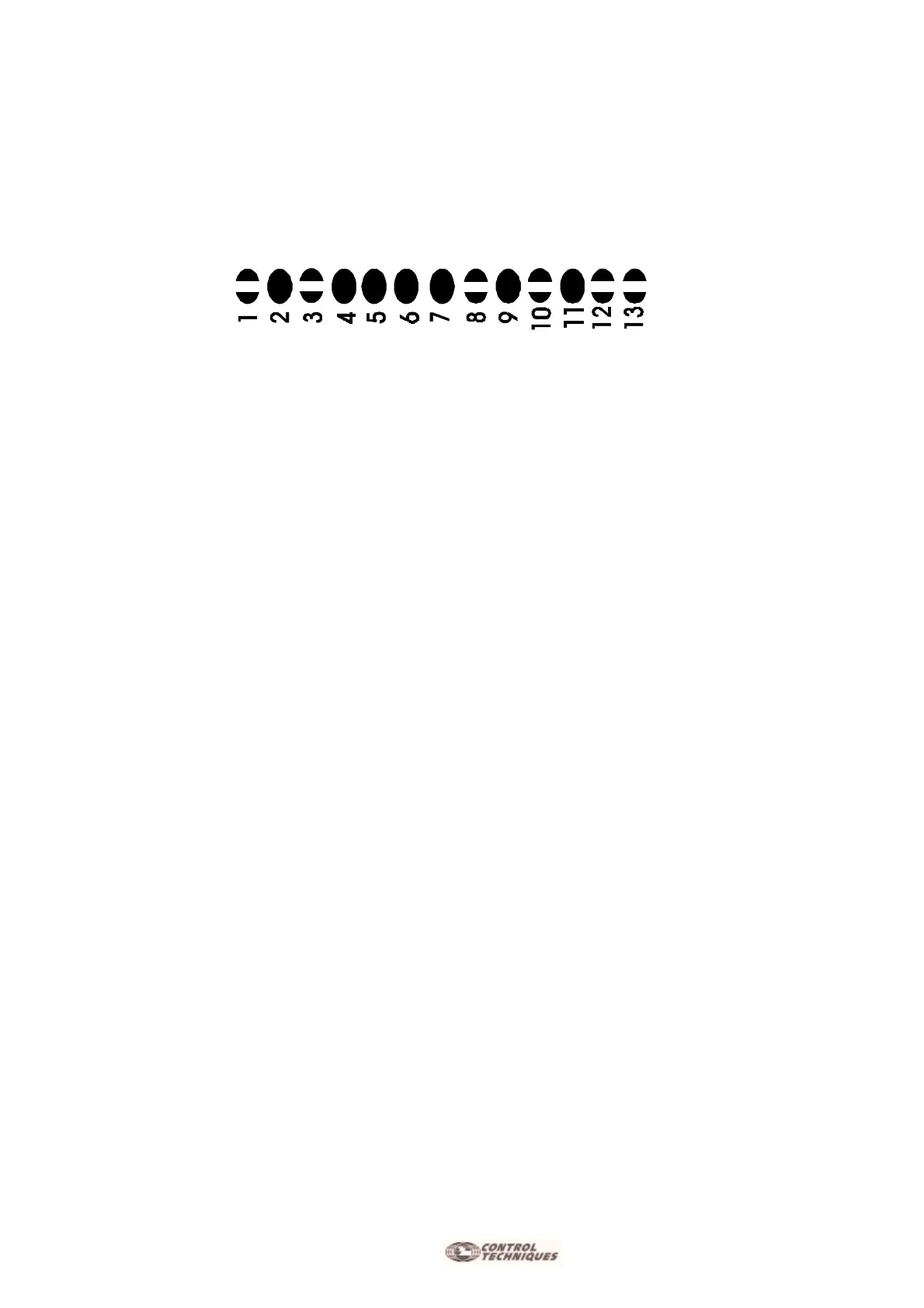
13 Solder Links are present (in the Adj. Zone) with which it's possible to enable or disable funcitons or parts
of the MiniAx. Verify the corresponding solder links closings required by the drive.
The Drive is furnished with the following Standard configuration of closed solder links:
Indicated below are the solder links that are to be opened or closed in accordance with the desired funtions.
S1
e
S3
Normally open. (See Chapter 5.7 “Ramp Time Adjustment”).
S2
Normally closed. (See Chapter 5.7 ““Ramp Time Adjustment”).
S4
Normally closed. If Open - disable the Encoder or Hall Effect speed feedback if selected.
S5
Normally closed. (Standard constant RKV=100Kohm , CKV= 47nF)
If Open - You must insert the NEW Dynamic Constant CKV, RKV on the persalization base.
(Adjustment reserved for Qualified Personnel Only ! )
S6
Normally closed. If Open - you must insert the New GAIN resistor. (Static Gain). Standard value= 22ohm
S7
Normally closed. If Open - you must insert the Dynamic Constant CKI, RKI on the personalization base.
(Standard constant RKI=220 Kohm , CKI= 2,2nF)
(Adjustments Reserved for Qualified Personnel Only!)
S8
Normally open. If Closed, when the IN protection is activated the green OK LED goes off and is unable to
allow the Drive OK LED to come on.
S9
Normally closed.(Encoder Feedback option). If open, you must configure the Speed feedback from the
Hall Effect Signal.
S10
Normally open. (Hall Effect 120° option). If Closed - you must enable the drive for Hall Effect 60°.
S11
Normally closed. If Open, the alarm protection for missing Hall Effect Signals will not disable the drive.
S12
-
S13
Normally open. (Configured for Drive signal with positive logic >+8V max 24V.). If Closed -
configure signal with negative logic. (Enable with zero GND Voltage).
 Loading...
