Safety
Information
Product
Information
Mechanical
Installation
Electrical
Installation
Getting
Started
Menu 0
Running
the motor
Optimisation Macros
Advanced
Parameters
Technical
Data
Diagnostics
UL Listing
Information
Unidrive User Guide 175
Issue Number: 9 www.controltechniques.com
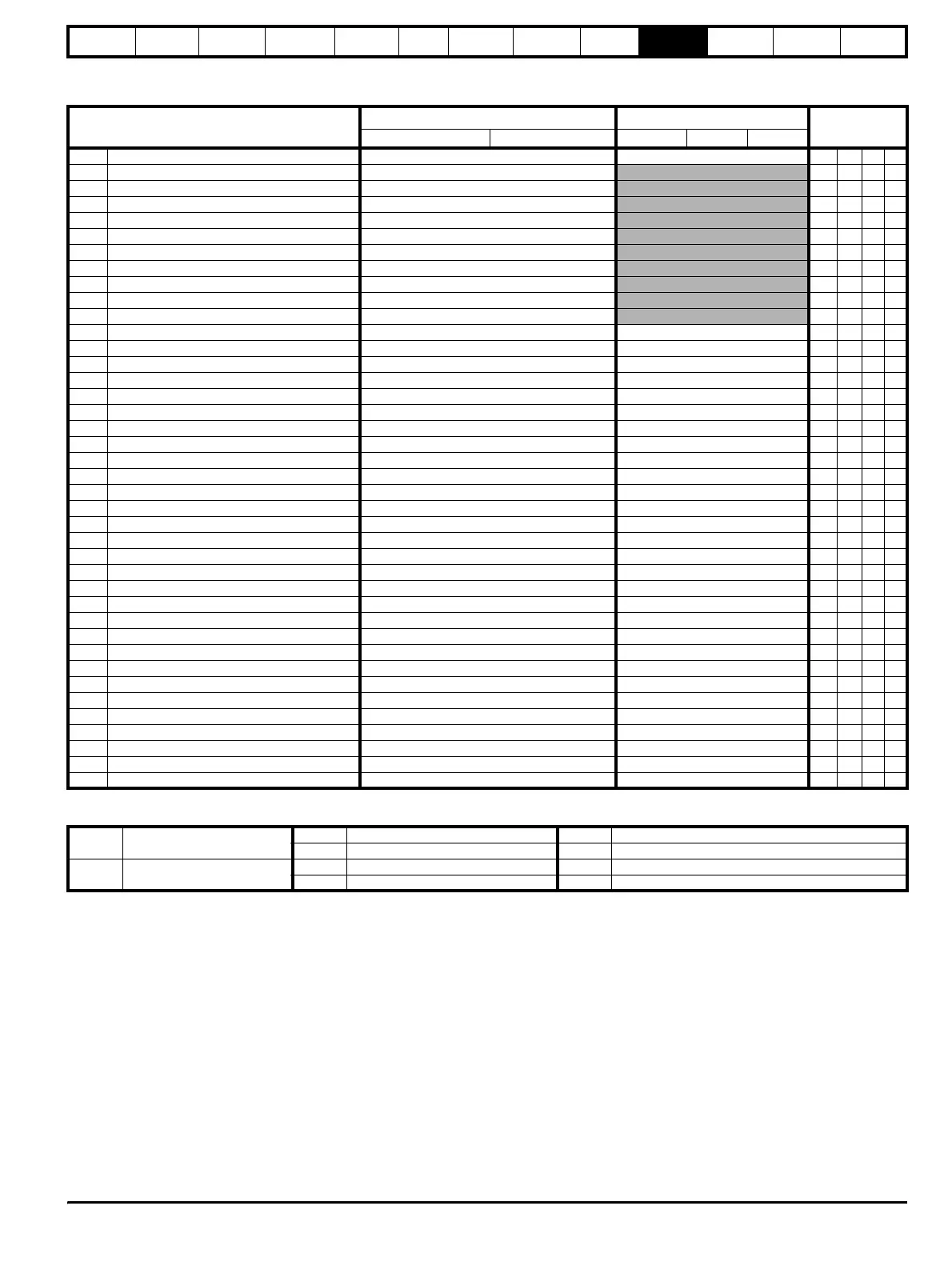
UD50 Additional I/O small option module parameter
list
Parameter
Range(
Ú) Default(Ö)
Type
OL CL OL VT SV
16.01
Option module code 0 to 100 1 RO Uni P
16.02 Relay 2 output indicator 0 or 1 RO Bit P
16.03 Relay 3 output indicator 0 or 1 RO Bit P
16.04 Analog input 4 ±100.0 % RO Bi P
16.05 Analog input 5 ±100.0 % RO Bi P
16.07 Logic input F7 / Output 7 indicator 0 or 1 RO Bit P
16.08 Logic input F8 / Output 8 indicator 0 or 1 RO Bit P
16.09 Logic input F9 / Output 9 indicator 0 or 1 RO Bit P
16.10 Logic input F10 0 or 1 RO Bit P
16.11 Logic input F11 0 or 1 RO Bit P
16.12 Logic input F12 0 or 1 RO Bit P
16.13 Analog input 4 scaling 0.000 to 4.000 1.000 RW Uni
16.14 Analog input 4 invert bit 0 or 1 0 RW Bit
16.15 Analog input 4 destination Pr 0.00 to Pr 20.50 Pr 0.00 RW Uni R P
16.16 Analog input 5 scaling 0.000 to 4.000 1.000 RW Uni
16.17 Analog input 5 invert bit 0 or 1 0 RW Bit
16.18 Analog input 5 destination Pr 0.00 to Pr 20.50 Pr 0.00 RW Uni R P
16.19 DAC Output 3 source Pr 0.00 to Pr 20.50 Pr 0.00 RW Uni R P
16.20 DAC Output 3 scaling 0.000 to 4.000 1.000 RW Uni
16.21 F7 input destination / output source Pr 0.00 to Pr 20.50 Pr 0.00 RW Uni R P
16.22 F7 input/output invert 0 or 1 0 RW Bit
16.23 F7 output enable 0 or 1 0 RW Bit R
16.24 F8 input destination / output source Pr 0.00 to Pr 20.50 Pr 0.00 RW Uni R P
16.25 F8 input/output invert 0 or 1 0 RW Bit
16.26 F8 output enable 0 or 1 0 RW Bit R
16.27 F9 input destination / output source Pr 0.00 to Pr 20.50 Pr 0.00 RW Uni R P
16.28 F9 input/output invert 0 or 1 0 RW Bit
16.29 F9 output enable 0 or 1 0 RW Bit R
16.30 F10 input destination Pr 0.00 to Pr 20.50 Pr 0.00 RW Uni R P
16.31 F10 input invert 0 or 1 0 RW Bit
16.32 F11 input destination Pr 0.00 to Pr 20.50 Pr 0.00 RW Uni R P
16.33 F11 input invert 0 or 1 0 RW Bit
16.34 F12 input destination Pr 0.00 to Pr 20.50 Pr 0.00 RW Uni R P
16.35 F12 input invert 0 or 1 0 RW Bit
16.36 Relay 2 source Pr 0.00 to Pr 20.50 Pr 0.00 RW Uni R P
16.37 Relay 2 output invert 0 or 1 0 RW Bit
16.38 Relay 3 source Pr 0.00 to Pr 20.50 Pr 0.00 RW Uni R P
16.39 Relay 3 output invert 0 or 1 0 RW Bit
16.40 Logic input polarity 0 or 1 0 RW Bit R P
16.41 Open collector outputs 0 or 1 0 RW Bit R P
RO Read Only parameter
Uni Unipolar variable parameter R Reset required for new value to take effect
Bi Bipolar variable parameter S New parameter-value saved at power-down
RW Read / Write parameter
Txt Text variable parameter P Protected; forbidden as destination parameter
Bit Bit parameter FLC Full-load current (max. continuous), Pr
11.32 {0.33}