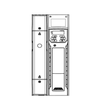
Do you have a question about the Control Techniques Unidrive 1402 and is the answer not in the manual?
Critical safety information regarding electrical hazards associated with the drive.
Guidelines for safe system integration and personnel protection.
Details on drive output current, power ratings, and derating conditions.
Overview of available operating modes like Open Loop, Closed Loop Vector, and Servo.
Crucial safety instructions for mechanical installation of the drive.
Ensuring safe electrical installation practices under normal and fault conditions.
Information on surface and through-hole mounting for Unidrive sizes 1 to 5.
Guidelines for planning the enclosure layout and sizing.
Guidance on calculating required enclosure size based on heat dissipation.
Formula and steps to calculate minimum unobstructed surface area for heat dissipation.
Method to calculate minimum required ventilating air volume for equipment.
Requirements for maintaining adequate airflow for drive cooling.
Specific ventilation needs for the Unidrive Size 5 power module.
Information on power terminals and their locations.
Specified tightening torques for power and ground terminals.
Recommendations for regular checks to ensure drive and installation reliability.
Guidance on electrically installing the drive.
How to electrically install the drive, including power connections.
Specifications for AC supply voltage, phases, imbalance, and frequency.
Requirements for connecting the drive to the system ground.
Details on the drive's output circuit protection and motor protection features.
Information on meeting EMC standards for power drive systems.
General guidelines for EMC enclosure layout and earth/ground connections.
Specific points for EMC compliance related to grounding and clearances.
Overview of Unidrive control connections and terminal functions.
Details on connecting encoders, including quadrature encoders.
Diagrams and specifications for connecting quadrature encoders.
Steps to configure a Unidrive size 5 system.
Procedure for saving the drive configuration after setup.
Introduction to setting up and operating the Unidrive.
Overview of keypad buttons for navigation and control.
Explanation of the drive's parameter structure and navigation.
Procedure for changing the drive's operating mode and parameter defaults.
Steps to save parameter values to the drive.
Procedure to restore drive parameters to factory default values.
Security levels for accessing drive parameters.
Overview of Menu 0 parameters for basic setup.
Detailed parameter descriptions for Unidrive variants.
Parameter descriptions for Unidrive variants, excluding VTC.
Specific parameter descriptions for Unidrive VTC.
Comprehensive descriptions of all Menu 0 parameters.
Details on configuring Menu 0 parameters, including saving and restoring defaults.
Setting minimum and maximum frequency/speed limits for the drive.
Configuration of ramps, speed references, and current limits.
Configuration of voltage boost and speed-loop PID parameters.
Configuration of jog functions, ramp modes, and stop modes.
Parameters related to motor characteristics like poles, voltage, current, and frequency.
Procedure for selecting and changing the drive's operating mode.
Guidance on starting and running the motor with the Unidrive.
Basic steps for setting up the drive to run the motor.
Procedure for selecting the drive's operating mode.
Step-by-step commissioning procedures for different operating modes.
Step-by-step guide for commissioning in open-loop mode.
Step-by-step guide for commissioning in closed-loop vector mode.
Step-by-step guide for commissioning in servo mode.
Using PC software for drive commissioning.
Commissioning an open-loop drive using PC software.
Commissioning an induction motor without feedback device.
Commissioning a closed-loop drive using PC software.
Commissioning an induction motor with speed feedback.
Procedure for performing the drive's autotune function.
Steps to save parameter values in the drive.
Commissioning a servo drive using PC software.
Commissioning a servo motor with speed and position feedback.
Guidance on optimizing drive performance.
Parameters for configuring the motor map for optimal control.
Information on optimizing open-loop motor control using map parameters.
Using slip compensation to optimize motor rated speed.
Optimizing closed-loop vector motor control parameters.
Procedure for performing the autotune test for motor parameter measurement.
Details on slip optimization for constant monitoring and compensation.
Tuning current loop gains for optimal performance.
Tuning speed loop gains for optimal performance and stability.
Method for tuning speed loop gains using an oscilloscope.
Control parameters and autotune procedure for servo motors.
Parameters controlling current limits for motoring, regenerating, and symmetrical operation.
How the drive models motor temperature and provides protection.
Overview of application macros for simplifying drive setup.
Procedure for loading application macros into the drive.
Terminal connection changes for specific macros.
Logic diagrams and parameter changes for Macro 1.
Reference to advanced parameters for detailed configuration.
Parameters for setting speed references and limits.
Parameters for configuring acceleration and deceleration ramps.
Configuration of speed feedback and frequency slaving.
Parameters for controlling motor current.
Parameters related to machine control functions.
Configuration of analog inputs and outputs.
Configuration of digital inputs and outputs.
Information on status indications and trip logging.
Logic diagrams and parameters for programmable PID control.
Configuration of smooth acceleration and deceleration profiles.
Explanation of different torque control modes.
Details on various stop modes like Coast, Ramp, and Injection braking.
Details on mains loss modes for drive operation.
Procedure for starting the drive with a spinning motor.
Settings for different position loop modes.
Technical specifications and data for the Unidrive.
Drive current ratings at various ambient temperatures and switching frequencies.
Summary of the drive's EMC performance.
Information on diagnosing drive faults and status.
Table of trip codes and their diagnoses.
List of drive alarms and their conditions.
| Model | Unidrive 1402 |
|---|---|
| Output Voltage | 0 to Input Voltage |
| Frequency Range | 0 to 400Hz |
| Communication Protocols | CANopen, Modbus RTU |
| Protection | Overcurrent, Overvoltage, Undervoltage, Overtemperature, Short Circuit |
| Enclosure Rating | IP20 |


