EasyManua.ls Logo

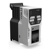
Control Techniques Unidrive 1405

Control Techniques Unidrive 1405
208 pages
To Next Page IconTo Next Page
Loading...
EF
www.controltechniques.com
User Guide
Unidrive
Model sizes 1 to 5
Universal Variable Speed AC Drive
for induction and servo motors
Part Number: 0460-0083-09
Issue Number: 9

Table of Contents

Question and Answer IconNeed help?

Do you have a question about the Control Techniques Unidrive 1405 and is the answer not in the manual?

Control Techniques Unidrive 1405 Specifications

General IconGeneral
BrandControl Techniques
ModelUnidrive 1405
CategoryController
LanguageEnglish

Summary

How to use this User Guide

Safety information

General safety information is provided in Chapter 1, page 7.

Safety Information

Warnings, Cautions and Notes

Information to ensure correct operation and avoid hazards.

Electrical safety - general warning

Warning about severe electrical shock, burns, and lethal hazards.

System design and safety of personnel

Drive as a component, safety hazards, installation by trained personnel.

Environmental limits

Compliance with transport, storage, installation, and use instructions.

Compliance with regulations

Installer responsibility for regulations, wiring, protection, and earth connections.

Product Information

Ratings

Table of 200V and 400V drive ratings, including current and overload information.

Operating modes

Lists and explains the different operating modes available for Unidrive.

Open Loop mode (OL)

For standard AC induction motors, V/f and open loop vector modes.

Closed loop vector mode (VT)

For motors with speed feedback, directly controls rotor speed.

Servo (SV)

For brushless motors with speed and position feedback, controls speed and position.

Mechanical Installation

Safety information

Follow mechanical and electrical installation instructions carefully.

Planning the installation

Considers access, environmental protection, cooling, electrical safety, fire protection, and EMC.

Terminal cover removal

Instructions for removing terminal covers and warnings about isolation devices and stored charge.

Option module fitting removal

Mounting methods

Enclosure

Enclosure Layout

Diagram showing recommended clearances for installing equipment within an enclosure.

Enclosure sizing

Guidelines for calculating enclosure size and heat dissipation.

Electrical safety

Fire protection

Electromagnetic compatibility

Ventilation

Ventilation requirements for the Size 5 power module

Details ventilation requirements for the size 5 power module, including fan options.

Power terminals

Location of power and ground terminals

Diagrams showing the location of power and ground terminals for Unidrive sizes 1-4 and size 5.

Terminal sizes and torque settings

Routine maintenance

Electrical Installation

Power connections

Diagrams and safety warnings for power connections for Unidrive sizes 1-2.

Unidrive Size 3 to 4 power connections

Unidrive size 5 control power module connections

AC supply requirements

Ground connections

Output circuit and motor protection

Cable types and lengths

Cable types and maximum lengths to avoid loading on the drive output.

Braking

Minimum resistances and power ratings

Table of minimum resistance and peak power ratings for braking resistors.

Ground leakage

Use of residual current device (RCD)

Types of ELCB/RCD suitable for Unidrive and their applications.

EMC (Electromagnetic compatibility)

Compliance with EN61800-3 (standard for Power Drive Systems)

Guidelines for meeting EN61800-3 standard based on operating environment.

EMC - General requirements

Feedback device cable shielding

EMC - Compliance

Variations in the EMC wiring

Control connections

Figure 4-15 Unidrive default terminal functions (except Unidrive VTC)

Figure 4-16 Unidrive VTC default terminal functions (European and USA)

Encoder connections

Quadrature encoder connections

Diagram showing default configurations for quadrature encoder connections.

Configuring a Unidrive size 5 system

Configuring the power modules

Procedure for configuring power modules, including address switches.

Configuring the control module

Saving the configuration

Getting Started

Keypad operation

Explanation of keypad layout and operation of control buttons.

Menu structure

Changing the operating mode

Saving parameters

Parameter security

Standard security

Prevents access to advanced menu parameters, with options to open, close, or disable.

User security

Prevents write access to all parameters except security code; options to set, open, close, or disable.

Menu 0

Menu 0 full descriptions

Speed limits

Setting minimum and maximum output frequency/speed for open and closed-loop operation.

Ramps, Speed reference selection, Current limit

Setting acceleration, deceleration rates, reference selection, and current limit.

Voltage boost (open-loop), Speed-loop PID gains (closed-loop)

Motor parameters

Operating-mode selection

Running the motor

Quick start set-up

Basic connections and minimal parameter settings for running the drive.

Basic connections

Shows basic connections for drive control methods (terminal, keypad).

Selecting the operating mode

Procedure for selecting the operating mode and resetting parameters.

Quick start set-up

Basic connections for running the drive in each operating mode.

Figure 7-1 Minimum connections to get the motor running in any operating mode

Quick Start commissioning

Open loop mode (including VTC variant)

Step-by-step guide for commissioning in open-loop mode for induction motors.

Closed loop vector mode

Servo

Quick start P.C. commissioning (UniSoft VTCSoft)

Closed Loop Vector

Servo

Optimisation

Motor map parameters

Parameters related to the motor, defining its characteristics for optimal performance.

Pr 0.40 5.12 Autotune

Pr 5.27 Slip compensation and Pr 0.45 5.08 Motor rated speed

Closed loop vector motor control

Pr 5.27 Slip optimisation

Pr 4.13 4.14 Current loop gains

Pr 3.10 3.11 3.12 Speed loop gains

Servo motor control

Current limits

Macros

How to load a macro

Advanced Parameters

Menu 1: Speed references and limits

Menu 2: Ramps (accel. decel.)

Menu 3: Speed feedback frequency slaving

Menu 4: Current control

Menu 5: Machine control

Menu 7: Analog IO

Menu 8: Digital IO

Menu 10: Status flags trip log

Advanced Features

Stop Modes

Catch a spinning motor

Position loop modes

Cable sizes and fuses

Electromagnetic compatibility (EMC)

Diagnostics

Trip indications

Lists trip codes, their diagnosis, and related terminals.

It.AC [I x t] thermal overload in the motor

OA Control PCB over temperature

Oh1 IGBT junction over temperature (based on the drive thermal model)

Oh2 Heatsink over temperature

OI.AC Over Current in output stage

OI.AC n Over current in the output stage of module n

Ot HS n Heatsink over temperature in module n

OU Over Volts on the DC bus

OU.SPd Over speed

PS Internal power supply fault

th Motor thermistor over temperature

UU Under Volts

HF - Hardware fault trip codes

Alarm indications

Displaying the trip history

Related product manuals