Safety
Information
Product
Information
Mechanical
Installation
Electrical
Installation
Getting
Started
Menu 0
Running
the motor
Optimisation Macros
Advanced
Parameters
Technical
Data
Diagnostics
UL Listing
Information
Unidrive User Guide 63
Issue Number: 9 www.controltechniques.com
5.11 Serial Communications
5.11.1 Introduction
The Unidrive has an optional serial communications interface in the form
of the UD71 serial communications module. This module has a fully
optically isolated 4 wire or 2 wire EIA485 interface and an EIA232
interface. (The EIA232 interface should be used for commissioning
purposes only.)
5.11.2 Serial communications module hardware
connections
See Figure 3-5 on page 15 for information regarding installing the UD71
serial communications large option module in the drive.
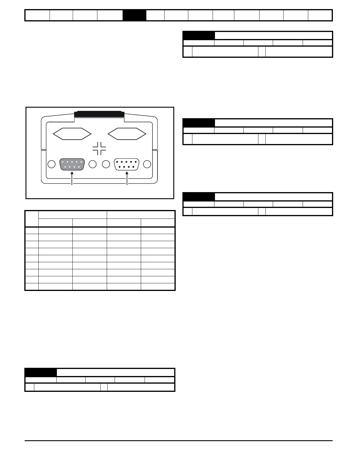
Figure 5-5 Location of communication interfaces
Table 5-1 Serial communications connections
* Pins 2 and 3, and pins 6 and 7 must be connected together in 2 wire
EIA485 mode.
** Depending on the host software being used, it may only be necessary
to connect pins 2, 3 and 5 when using the EIA232 interface.
When connecting EIA232 interface on the UD71 serial communications
module to the 9 pin serial port on a PC, a 9 pin male D-type to 9 pin
female D-type serial extension cable can be used.
5.11.3 Serial communications set-up parameters
The following parameters need to be set according to the system
requirements.
Defines the unique address for the drive. Any number in the permitted
range 0.0 to 9.9 which has a zero in it, should not be used as these are
used to address groups of drives.
This is the mode of operation of the serial port.
ANSI 2 (0) Standard 2 wire EIA485 using ANSI protocol
ANSI 4 (1) Standard 4 wire EIA485 using ANSI protocol
OUtPUt (2) Output variable defined by Pr 11.27
INPUt (3) Input variable defined by Pr 11.27
OUtPUt (2) and INPUt (3) are used to transfer a variable parameter from
one drive to another. See the Unidrive Advanced User Guide for more
information.
Used in 2 or 4 wire ANSI modes to select the communications port baud
rate.
4800 (0) 4800 baud
9600 (1) 9600 baud
19200 (2) 19200 baud
2400 (3) 2400 baud
If 2 wire EIA485 communications is being used then a delay is required
between the drive receiving data and then responding to allow the
device that sent the request to changes its buffers from transmit to
receive.
Pin
EIA485 Interface EIA232 Interface
4 wire mode 2 wire mode UD71 Host PC
10V 0V CD CD
2 TX\ TX\ RX\* TXD** RXD**
3 RX\ TX\ RX\* RXD** TXD**
4 Not connected Not connected DTR DTR
5 Not connected Not connected 0V** 0V**
6 TX TX RX* DSR DSR
7RX TX RX* RTS RTS
8 Not connected Not connected CTS CTS
9 Not connected Not connected NC RI
11.23 Serial comms. address
RW Uni P
Ú
0.0 to 9.9
Ö
1.1
AB
DC
EIA485 Interface
male 9 pin D-t
pe
EIA232 Interface
Female 9 pin D-t
pe
11.24 Serial comms. mode
RW Txt P
Ú
ANSI 2 (0), ANSI 4 (1), OUtPUt (2),
INPUt (4)
Ö
ANSI 4 (1)
11.25 Serial comms. baud rate
RW Txt P
Ú
4800 (0), 9600 (1), 19200 (2),
2400 (3)
Ö
4800 (0)
11.26 Serial comms. two-wire mode delay
RW Uni P
Ú
0 to 255 ms
Ö
0