Unidrive
LV
model sizes 1 to 3 Installation Guide
Issue code: uliu1
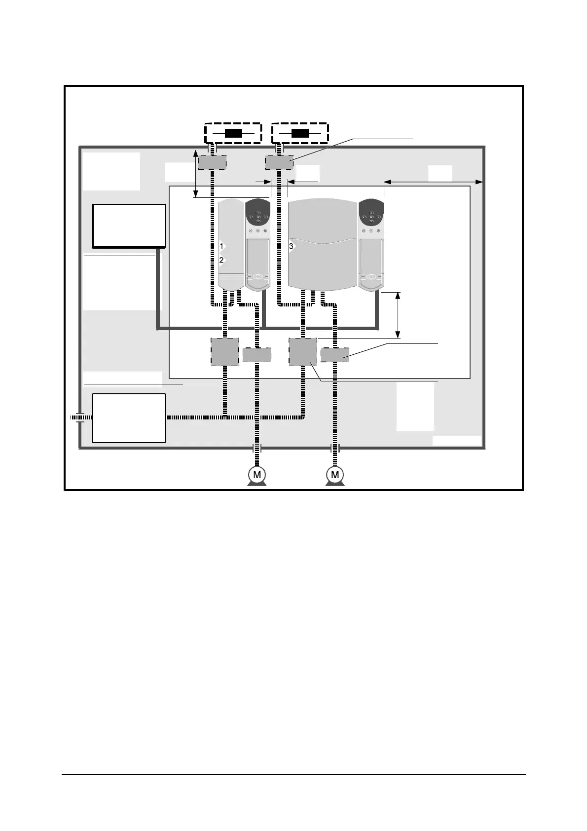
2-12 Installing the Drive
≥100mm
(4in)
Optional braking resistors as required for the Drives
External: Mount on top surface of enclosure.
Internal: Mount in top part of enclosure.
System controller
Locate as required.
Signal cables
Plan for all signal
cables to be routed at
least 300mm (12in)
distant from any
power cable.
AC supply isolator,
contactor, and
fuses or MCBs
Locate as required.
Enclosure
Drives
Ensure minimum
clearances are
respected.
Back-plate
≥5mm
(¼in)
≥100mm
(4in)
Alternative
location of
fuses or
MCBs
Locate as
required.
≥5mm
(¼in)
Power cables
Location
of optional
terminal
block
Overload protection
device
Figure 2–4 Recommended layout for routine EMC precautions (wiring recommendations
are given in Figure 2–21)
 Loading...