Unidrive
LV
model sizes 1 to 3 Installation Guide
Issue code: uliu1
Installing the Drive 2-37
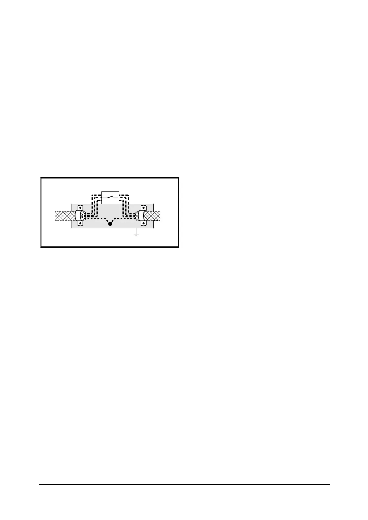
Using a motor isolator-switch
The motor cable shields should be connected by a
very short conductor having a low inductance. The
use of a flat metal coupling-bar is recommended;
conventional wire is not suitable.
The shields should be bonded directly to the
coupling-bar using uninsulated metal cable-clamps.
Keep the length of the exposed power conductors
to a minimum and ensure that all sensitive
equipment and circuits are at least 0.3m (12 in)
away.
The coupling-bar may be grounded to a known
low-impedance ground nearby, for example a large
metallic structure which is connected closely to the
Drive ground.
Isolator
Coupling bar
From the
Drive
To the
motor
(If required)
(Refer to Key to symbols in Figure 2–22)
Figure 2–25 Connecting the motor cable to
an isolator switch
2.9 Signal connections
The signal connections to be made depend on the
method of control to be used. Refer to Chapter 2
Getting Started, Chapter 3 Setting up the Drive and
Appendix C Signal Connections in the User Guide.
 Loading...