Unidrive
LV
model sizes 1 to 3 Installation Guide
Issue code: uliu1
Installing the Drive 2-17
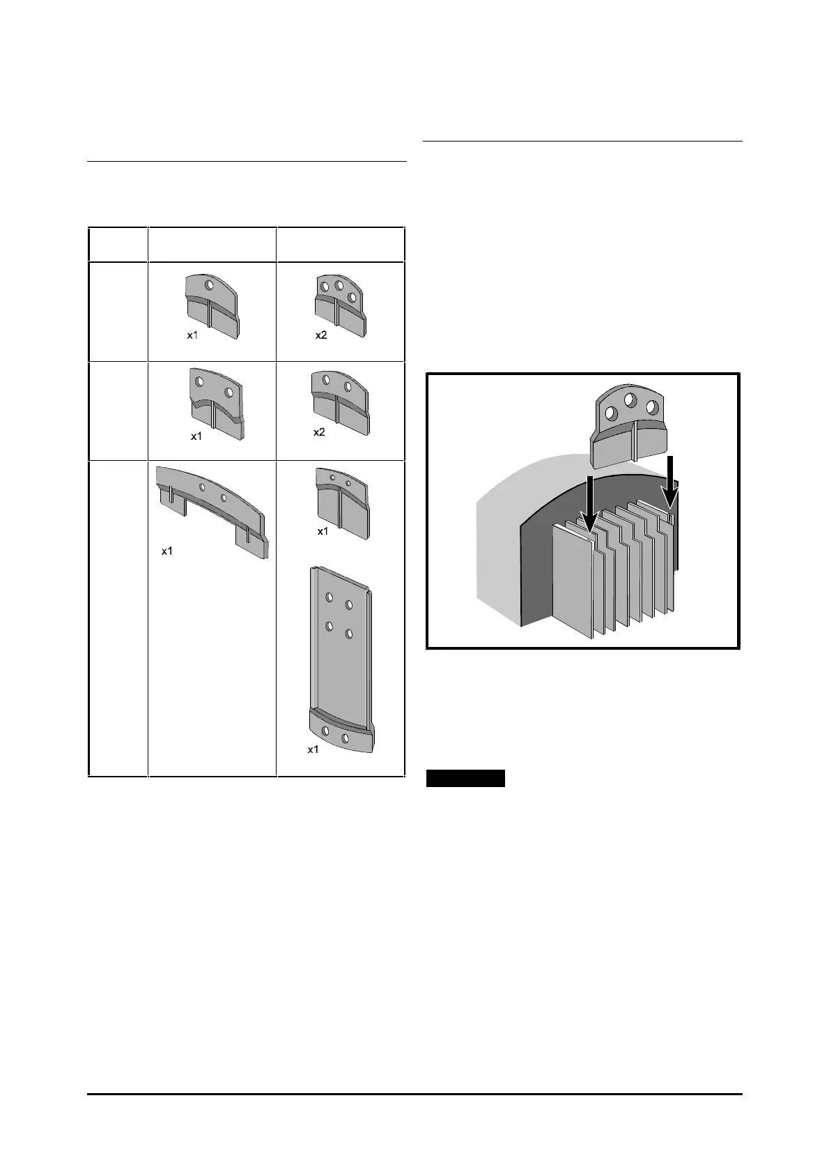
Mounting brackets supplied
with the Drive
Table 2–10 General views of the
mounting brackets
Model
size
Through-panel Surface
1
Upper and lower
2
Upper and lower
3
Upper
Lower
Rear view of the brackets. The brackets are not shown to
scale.
Fixing hole size: M6 (
1
/
4
in)
Surface-mounting the Drive
1. Use the two surface-mounting brackets. These
are manufactured from metal. Ensure the
brackets make direct electrical contact with the
back-plate; for example, tap M6 (
1
/
4
in)
threaded holes in the back-plate in the positions
shown in Figure 2–10 to accept the mounting
screws. (For model size 1, you may use the
central or, preferably, the two outer screw
holes in the mounting bracket.)
2. Insert the surface mounting brackets into the
slots in the top and bottom of the Drive
heatsink, as shown in Figure 2–9.
Figure 2–9 General representation showing
the fitting of a surface mounting
bracket in a heatsink
3. Retain the mounting brackets to the back-plate
using electrically conducting screws.
Note
When surface mounting a model size 3,
allow a clearance of 150mm (6in) above the
Drive; this is required for dismounting. A
minimum clearance of 100mm (4in) is
required for ventilation.