Guide pas à pas pour l’Unidrive M100/M101/M200/M201/M300 11
Édition : 1
English Français Deutsch Italiano Español
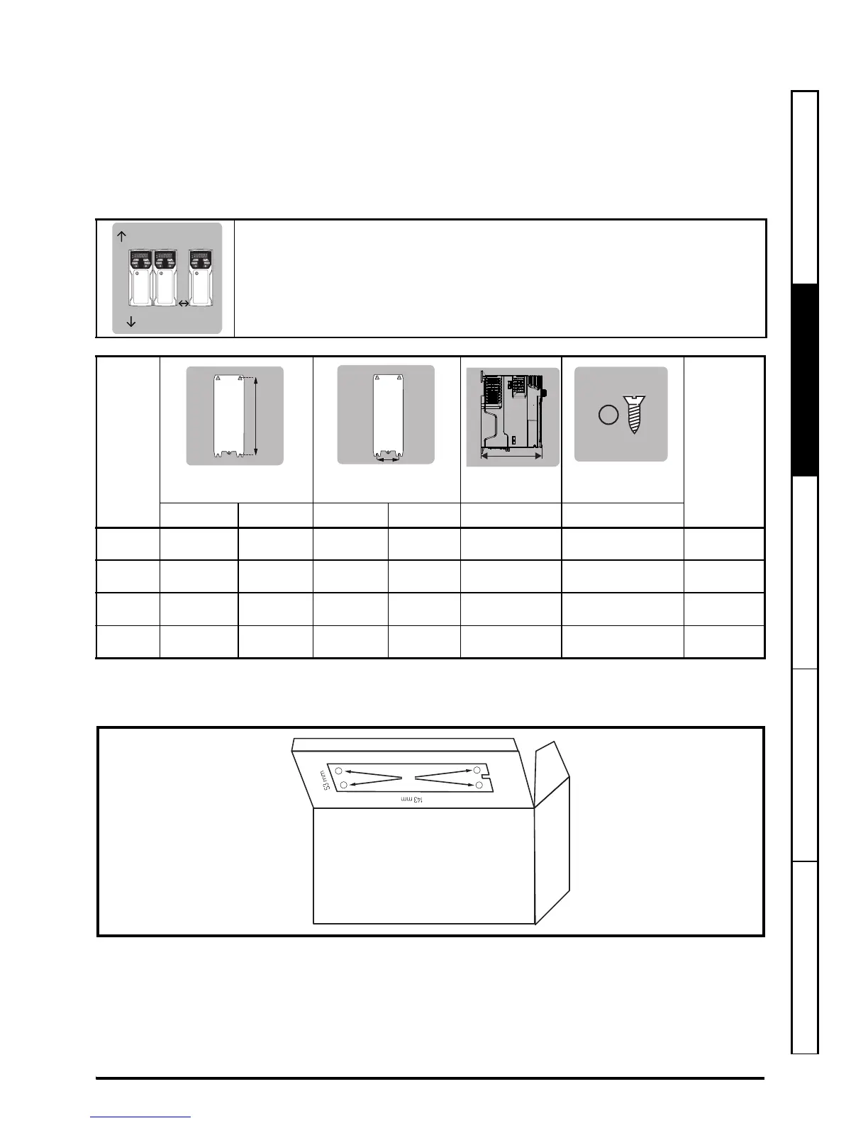
ÉTAPE 3 : Montage du variateur
Plage de température ambiante en fonctionnement :
- 20 à 60 °C
Un déclassement du courant de sortie peut être nécessaire pour des températures ambiantes >40 °C.
Consulter le Guide d’installation - Puissance (section 5.1). Pour les installations UL, la température ambiante
maximale autorisée est de 50 °C, quel que soit le déclassement appliqué.
Les variateurs peuvent être montés sans espacement entre eux. Prévoir un espacement minimum de 100 mm
au-dessus et au-dessous du variateur. Pour des informations concernant le déclassement applicable pour des
espacements inférieurs, se reporter à la section 3.4 du Guide d'installation - Puissance.
* Le Potentiomètre de référence de vitesse ajoute 11 mm supplémentaires à la profondeur totale pour les
variateurs Unidrive M101 et M201 uniquement.
Un gabarit de perçage pour le montage mural est fourni avec le variateur (voir l’illustration ci-dessous).
ÉTAPE 4 : Montage de l’étrier de mise à la terre
L’étrier de mise à la terre facilite la gestion des câbles après leur connexion au variateur. L’étrier est aussi utilisé
pour fixer le blindage des câbles à la terre afin de permettre la conformité CEM (voir la Figure 7-1).
Taille
Poids
HLP*Ø
Fixation Hors tout Fixation Hors tout Hors tout Diamètre
1 143 mm 160 mm 53 mm 75 mm 130 mm 5 mm 0,75 kg
2 194 mm 205 mm 55 mm 75 mm 150 mm 5 mm 1,3 kg
3 215 mm 226 mm 70,7 mm 90 mm 160 mm 5 mm 1,5 kg
4 265 mm 277 mm 86 mm 115mm 175mm 6mm 3,13kg