Unidrive M100/M101/M200/M201/M300 Guía detallada 41
Publicación: 1
English Français Deutsch Italiano Español
PASO 12: Puesta en marcha del motor
Solución de problemas
El accionamiento muestra un código de error cuando detecta una avería. Para localizar y resolver todos los códigos
de error, está disponible la aplicación ‘Diagnostic Tool (App)’ en las plataformas Microsoft, Android e iOS, mediante
la tienda ‘Apps’ de Smartphone / Tablet; busque ‘Control Techniques diagnostics tool in the Apps store’.
También puede descargar la ‘Diagnostic Tool (App)’ de ‘App Center’ de Control Techniques o consultar toda la
sección de diagnósticos en la Guía de consulta rápida, disponible para descarga en el sitio web de Control
Techniques o Leroy Somer.
Acción Detalles
Encendido Verifique:
• El accionamiento muestra: inh (terminales de activación abiertos)
Velocidades máxima
y mínima
Introduzca:
• Velocidad mínima en Pr 01 (Hz)
• Velocidad máxima en Pr 02 (Hz)
Velocidades de
aceleración y
deceleración
Introduzca:
• Velocidad de aceleración en Pr 03 (s/100 Hz)
• Velocidad de deceleración en Pr 04 (s/100 Hz)
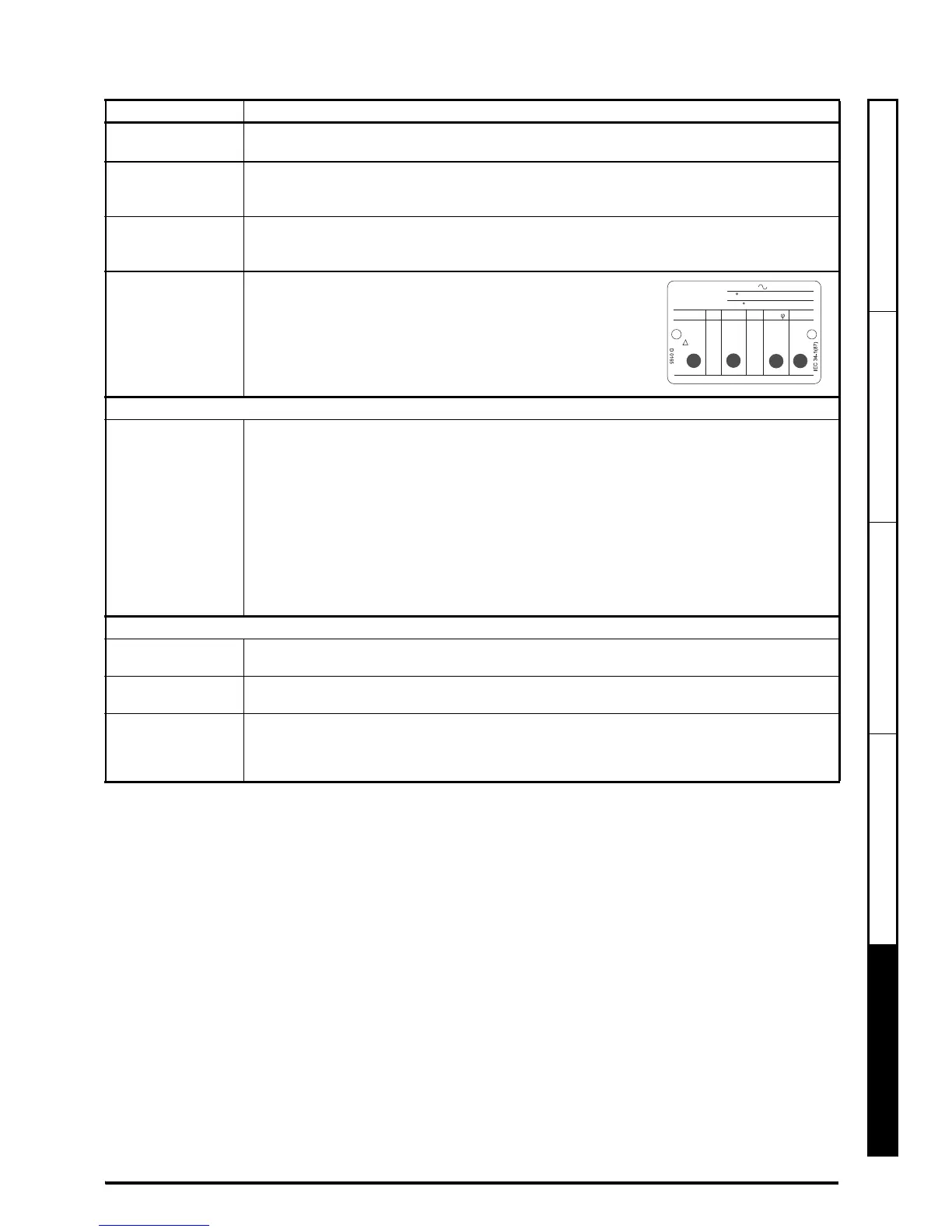
Detalles de la placa
de características del
motor
Preparado para el autoajuste
Autoajuste El accionamiento puede realizar un autoajuste estático o por rotación. El motor debe estar estático
antes de activar cualquier autoajuste y desconectado de la carga para el autoajuste por rotación.
Para realizar un autoajuste:
•Ajuste Pr38 = 1 para el autoajuste estático o Pr 38 = 2 para el autoajuste por rotación.
• Cierre la señal de activación del accionamiento (aplique +24 V al terminal 11 o a los
terminales 31 y 34 en Unidrive M300). El accionamiento muestra ‘rdy’.
• Indique una instrucción de marcha (aplique +24 V al terminal 12 – Marcha Adelante o
terminal 13 – Marcha atrás en Unidrive M100, M200 y M300; pulse la tecla de inicio del
teclado en M101, M201). En la pantalla parpadea la indicación ‘tuning’ mientras el
accionamiento realiza el autoajuste.
• Espere hasta que aparezca la indicación ‘inh’ y se detenga el motor.
• Elimine las señales de activación y de marcha del accionamiento.
Preparado para funcionar
Marcha El accionamiento está listo para hacer funcionar el motor. Cierre los terminales Marcha adelante o
Marcha atrás en Unidrive M100, M200 y M300 solamente.
Aumento y reducción
de la velocidad
El cambio de la referencia Frecuencia analógica seleccionada (Potenciómetro de referencia de
velocidad en M101 / M201) aumenta y reduce la velocidad del motor.
Parada Para detener el motor siguiendo la velocidad de deceleración seleccionada, abra el terminal
de marcha adelante o el terminal de marcha atrás en Unidrive M100, M200 y M300 solamente.
Si el terminal de activación se abre con el motor en marcha, la salida del accionamiento se
desactiva de inmediato y el motor marcha por inercia hasta detenerse.
 Loading...


