PoolWarden Manual www.poolwardentraining.com 530-205-4520 10
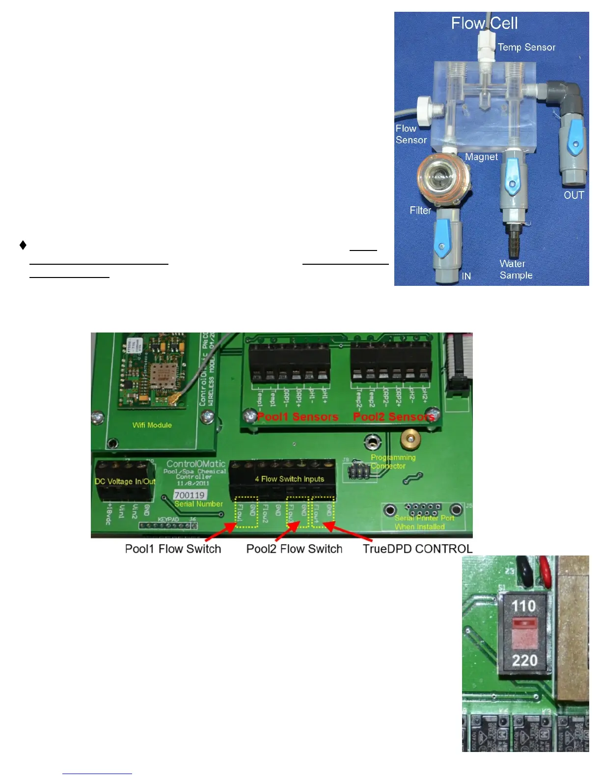
IMPORTANT NOTE: There needs to be just enough flow (0.5 gpm)
through the flow cell to raise the flow magnet inside the flow cell to
make contact with the flow sensor. To test this, turn the “input” shut-off
valve to the off position and watch the flow magnet drop from the flow
sensor. Next, turn the input shut-off valve back on and watch the flow
magnet rise to the flow sensor. If the flow magnet rises abruptly and
pings/knocks the flow cell acrylic then the flow is too high. To reduce
flow, perform the same exercise, but now open the shut-off valve slowly
and stop when you see the magnet “slowly” rise to make connection
with the flow sensor. Leave the shut-off valve in that position.
Sensor Wire Connection
If not pre-mounted, route the pH (Blue Sensor Wires), ORP (Red
Sensor Wires), flow sensor and temp sensor wires through the cable
grips at the bottom of controller and connect as labeled inside or as
indicated below in PICTURE 3. Note: Black wires are always
negative (-) and the Clear or Red wires are always positive (+).
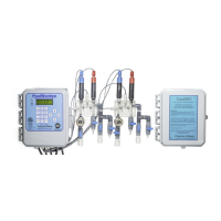
REQUIRED Flow Sensor Connections: Connect flow sensor wires
for pool #1 to flow switch 1 and connect flow sensor wires for pool #2
to flow switch 3.
⧫ Optional Flow Sensor Connections: Flow switch 2 & 4 are auxiliary switches for Pool #1 and Pool #2
respectively. For powered 3 wire digital flow meters or water level indicators use the 18VDC connection on
the left of the main board, note that it has a 1 amp fuse.
PICTURE 2
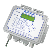
Supply 110/220 Vac Input Selection
The PoolWarden supports both 110 VAC and 220 VAC. For 110 VAC the power
cord includes a GFCI on the end of the cord that plugs in. For 220 VAC the cord
should be removed and the PoolWarden should be hardwired to a circuit breaker
with a GFCI by a licensed electrician. The cord can be returned to ControlOMatic for
a credit.
⧫ VAC Selector: The red switch in the center of the bottom circuit board must have
the switch notch up for 110 VAC, and down for 220 VAC. Incorrect selection will
damage the PoolWarden.
⧫ A good solid earth ground is required for PoolWarden to work properly. Without
a solid ground connection the sensors may drift.