8
CONTROL PANEL DIGITAL INPUT
The panel provides the analog and digital inputs defined below located in the Input Configuration
menu. The panel is shipped from the factory with the highlighted inputs enabled in the panel. Inputs
not highlighted need to be enabled/configured in the menu system to be used.
DIGITAL FUNCTIONS
The digital input in this model is dedicated to providing the remote start circuit with a signal. The
flex analog circuit can be used as a switch shutdown input if configured as such in the Input
Configuration menu.
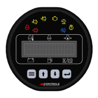
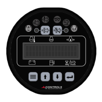
1) Alarm – Engine shutdown when active with display message as assigned. A red lamp will also
be illuminated.
2) Pre Alarm – Warning message will be displayed along with a yellow lamp when active.
DIGITAL FUNCTION MONITORING
Off / Always / Run – Describes when the parameter will be monitored for alarm conditions. Run refers
to when the engine is running. Off disables the alarm conditions. Always enables the alarm constantly
regardless of engine state.
DIGITAL FUNCTION DELAYS
Alarm Delay – The time period, after Sender Check Bypass, that the parameter must be on the alarm
condition before the alarm becomes latched.