Do you have a question about the Controls EMGRT1 and is the answer not in the manual?
Procedure for starting and stopping the engine manually via key switch and enter button.
Procedure for automatic start/stop using float circuits to control engine operation based on fluid levels.
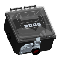
Describes the EMGRT1 as a microprocessor-based controller on a specific platform.
Details the polycarbonate enclosure's dimensions and NEMA rating.
Outlines the backlit digital display size and character dimensions.
Lists methods for auto start and stop, including single and dual float circuits.
Mentions available specific inputs and alarms like E-Stop and Fuel Level.
States the controller does not require a laptop for programming settings.
Describes the backlit digital display panel size and character dimensions.
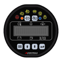
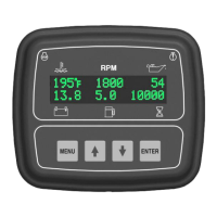
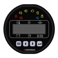
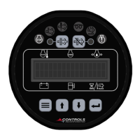
Lists the six full-time parameters displayed on the controller screen.
Explains the function of Menu and Enter buttons for menu access.
Explains the function of Up and Down buttons for menu navigation.
Details the Auto, Off, and Run positions of the key switch.
Identifies the 10 amp fuse and the amber/red indicator LEDs.
Describes the polycarbonate enclosure, its NEMA rating, and hinged door.
Details how the enclosure door is held by screws for internal access.
Lists plug & play connectors integrated into the enclosure.
Specifies the 16-pin Deutsch plug for the engine harness connection.
Describes the Pollack connector for single/dual float and its logic for start/stop.
Details the manual start process using the key switch and Enter button and shutdown via key.
Explains auto start/stop using normally open float contacts for engine control.
States that engine speed control or throttle control functionality is not available.
Describes how the controller shuts down the engine upon detecting faults, indicated by LED and message.
Lists specific faults like low oil pressure, high temperature, over speed, and low fuel level.
Explains monitoring of additional system inputs like E-Stop and float switches.
Details analog fuel level sender connection, scale, and pre-alarm/shutdown settings.
Describes digital inputs for low water and low oil level switches and their shutdown function.
Explains how faults are indicated (LED, message) and how to clear them by cycling power.
Provides a detailed pinout for the 16-pin Deutsch engine harness connector.
Details the pinout for the 4-pin Pollack float connector for single and dual float setups.
Explains how to enter and navigate controller menus using the keypad.
Describes the password screen for restricted editing and the process of editing parameters.
Outlines how to exit menu screens and the effect on edits and password state.
Step-by-step instructions for resetting the controller to factory default settings using JP10 pins.
Table detailing factory default settings for speed, oil pressure, temperature, fuel level, and battery.
Table showing factory default settings for cranks, duration, and optional digital inputs.
Instructions on how to calibrate the RPM display by adjusting circuit board settings.
Lists terminal connections for engine and system inputs, with pin numbers and descriptions.
Lists terminal connections for engine operation outputs, including fault and alarm signals.
Explains the voltage behavior of TTL outputs when active and inactive.
Lists specific TTL outputs such as shutdown indicators and engine run indicator.
Provides definitions for each dipswitch, noting which ones are used.
Explains the procedure for changing dipswitch settings and the need to cycle power.
Describes the function of the SCBS and the conditions required for its operation.
Details the sequence of events when the SCBS initiates an engine start for battery charging.
Outlines the seller's warranty for products, covering defects and limitations.
Specifies limitations on the seller's liability for damages arising from product use or warranty breaches.
| Brand | Controls |
|---|---|
| Model | EMGRT1 |
| Category | Controller |
| Language | English |