CONTROLS, INCORPORATED
CONTROL SYSTEMS & SOLUTIONS
- 10 -
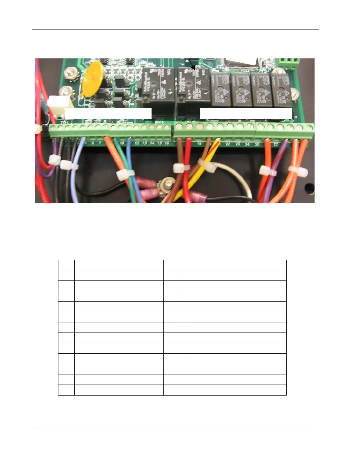
10) Terminal Strip Connections
10.1 Below is a list of connection definitions for circuit board mounted terminal connectors
10.1.1 PCB Version 1410-000 V1.4.
1 Battery Positive 16
2 Battery Negative 17 Power to Fuel System (10A DC Max)
3 MPU+ 18 Battery Positive Relay Common
4 MPU- 19
5 Fuel Level Sender 240-33 ohm 20 Alternator Excite (D+)
6 Low Water Level Switch 21 Power Crank Solenoid (10A DC Max)
7 Low Oil Level Switch 22 Fault Common
8 Remote Start Input 23 Fault Normally Open
9 Engine Temp Sender 24 Fault Normally Closed (5A DC max)
10 25 Pre Alarm Common
11 Oil Pressure Sender 240-33 ohm 26 Pre Alarm Normally Open (5A DC max)
12 Emergency Stop 27
28 Glow Plug Normally Open (5A DC max)
Engine / System Inputs Engine Operation Outputs